The vehicle's on-board network is powered by the battery until the power plant starts. But it itself does not generate electrical energy. The battery is simply a container for electricity, which is stored in it and, if necessary, given to consumers. Afterwards, the expended energy is restored due to the operation of the generator, which produces it.
But even constant recharging of the battery from a generator is not able to completely restore the expended energy. This requires periodic charging from an external source rather than a generator.
Design and principle of operation of the charger
Chargers are used to produce. These devices operate from a 220 V network. In fact, the charger is a conventional electrical energy converter.
It takes the alternating current of the 220 V network, lowers it and converts it into direct current with a voltage of up to 14 V, that is, to the voltage that the battery itself produces.
Nowadays a large number of all kinds of chargers are produced - from primitive and simple ones to devices with a large number of various additional functions.
Chargers are also sold, which, in addition to possibly recharging the battery installed on the car, can also start the power plant. Such devices are called charging and starting devices.
There are also autonomous charging and starting devices that can recharge the battery or start the engine without connecting the device itself to a 220 V network. Inside such a device, in addition to equipment that converts electrical energy, there is also one, which makes such a device autonomous, although the battery of the device is also After each release of electricity, charging is required.
Video: How to make a simple charger
As for conventional chargers, the simplest of them consists of only a few elements. The main element of such a device is a step-down transformer. It lowers the voltage from 220 V to 13.8 V, which is the most optimal for charging the battery. However, the transformer only lowers the voltage, but converting it from alternating current to direct current is performed by another element of the device - a diode bridge, which rectifies the current and divides it into positive and negative poles.
Behind the diode bridge, an ammeter is usually included in the circuit, which shows the current strength. The simplest device uses a dial ammeter. In more expensive devices, it can be digital; in addition to the ammeter, a voltmeter can also be built-in. Some chargers have the ability to select voltage; for example, they can charge both 12-volt and 6-volt batteries.
Wires with “positive” and “negative” terminals come out of the diode bridge, which connect the device to the battery.
All this is enclosed in a housing, from which comes a wire with a plug for connecting to the network, and wires with terminals. To protect the entire circuit from possible damage, a fuse is included in it.
In general, this is the entire circuit of a simple charger. Charging the battery is relatively simple. The terminals of the device are connected to the discharged battery, but it is important not to mix up the poles. The device is then connected to the network.
At the very beginning of charging, the device will supply voltage with a current of 6-8 amperes, but as charging progresses, the current will decrease. All this will be displayed on the ammeter. If the battery is fully charged, the ammeter needle will drop to zero. This is the entire process of charging the battery.
The simplicity of the charger circuit makes it possible to manufacture it yourself.
Making your own car charger
Now let's look at the simplest chargers that you can make yourself. The first will be a device that is very similar in concept to the one described.

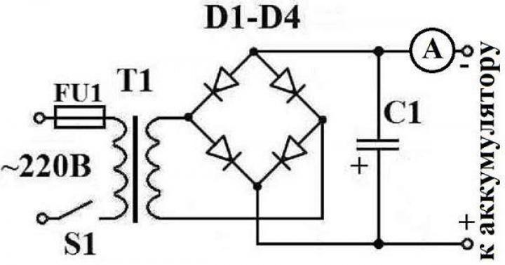
The diagram shows:
S1 - power switch (toggle switch);
FU1 - 1A fuse;
T1 - transformer TN44;
D1-D4 - diodes D242;
C1 - capacitor 4000 uF, 25 V;
A - 10A ammeter.
So, to make a homemade charger you will need a step-down transformer TS-180-2. Such transformers were used on old tube TVs. Its feature is the presence of two primary and secondary windings. Moreover, each of the secondary output windings has 6.4 V and 4.7 A. Therefore, in order to achieve the 12.8 V required for charging the battery, which this transformer is capable of, you need to connect these windings in series. For this, a short wire with a cross-section of at least 2.5 mm is used. sq. The jumper connects not only the secondary windings, but also the primary ones.
Video: The simplest battery charger
Next, you will need a diode bridge. To create it, 4 diodes are taken, designed for a current of at least 10 A. These diodes can be fixed on a textolite plate, and then they can be connected correctly. Wires are connected to the output diodes, which the device will connect to the battery. At this point, the assembly of the device can be considered complete.
Now about the correctness of the charging process. When connecting a device to a battery, do not reverse the polarity, otherwise you can damage both the battery and the device.
When connecting to a battery, the device must be completely de-energized. You can turn it on only after connecting it to the battery. It should also be disconnected from the battery after disconnecting from the network.
A heavily discharged battery cannot be connected to the device without a means that reduces the voltage and current, otherwise the device will supply a high current to the battery, which can damage the battery. An ordinary 12-volt lamp, which is connected to the output terminals in front of the battery, can act as a reducing agent. The lamp will light up when the device is operating, thereby partially absorbing the voltage and current. Over time, after the battery is partially charged, the lamp can be removed from the circuit.
When charging, you need to periodically check the state of charge of the battery, for which you can use a multimeter, voltmeter or load plug.
A fully charged battery, when checking its voltage, should show at least 12.8 V; if the value is lower, further charging is required to bring this indicator to the desired level.
Video: DIY car battery charger
Since this circuit does not have a protective housing, you should not leave the device unattended during operation.
And even if this device does not provide the optimal 13.8 V output, it is quite suitable for recharging the battery, although after about two years of using the battery, you will still need to charge it with a factory device that provides all the optimal parameters for charging the battery.
Transformerless charger
![]()
An interesting design is the circuit of a homemade device that does not have a transformer. Its role in this device is played by a set of capacitors designed for a voltage of 250 V. There must be at least 4 such capacitors. The capacitors themselves are connected in parallel.
A resistor is connected in parallel to the set of capacitors, designed to suppress the residual voltage after disconnecting the device from the network.
Next, you will need a diode bridge to operate with a permissible current of at least 6 A. It is connected to the circuit after a set of capacitors. And then the wires that will connect the device to the battery are connected to it.
Every motorist sooner or later has problems with the battery. I did not escape this fate either. After 10 minutes of unsuccessful attempts to start my car, I decided that I needed to purchase or make my own charger. In the evening, after checking out the garage and finding a suitable transformer there, I decided to do the charging myself.
There, among the unnecessary junk, I also found a voltage stabilizer from an old TV, which, in my opinion, would work wonderfully as a housing.

Having scoured the vast expanses of the Internet and really assessed my strengths, I probably chose the simplest scheme.

After printing out the diagram, I went to a neighbor who is interested in radio electronics. Within 15 minutes, he collected the necessary parts for me, cut off a piece of foil PCB and gave me a marker for drawing circuit boards. Having spent about an hour, I drew an acceptable board (the dimensions of the case allow for spacious installation). I won’t tell you how to etch the board, there is a lot of information about this. I took my creation to my neighbor, and he etched it for me. In principle, you could buy a circuit board and do everything on it, but as they say to a gift horse...
Having drilled all the necessary holes and displayed the pinout of the transistors on the monitor screen, I took up the soldering iron and after about an hour I had a finished board.

A diode bridge can be purchased on the market, the main thing is that it is designed for a current of at least 10 amperes. I found D 242 diodes, their characteristics are quite suitable, and I soldered a diode bridge on a piece of PCB.

The thyristor must be installed on a radiator, since it gets noticeably hot during operation.

Separately, I must say about the ammeter. I had to buy it in a store, where the sales consultant also picked up the shunt. I decided to modify the circuit a little and add a switch so that I could measure the voltage on the battery. Here, too, a shunt was needed, but when measuring voltage, it is connected not in parallel, but in series. The calculation formula can be found on the Internet; I would add that the dissipation power of the shunt resistors is of great importance. According to my calculations, it should have been 2.25 watts, but my 4-watt shunt was heating up. The reason is unknown to me, I don’t have enough experience in such matters, but having decided that I mainly needed the readings of an ammeter, and not a voltmeter, I decided on it. Moreover, in voltmeter mode the shunt noticeably warmed up within 30-40 seconds. So, having collected everything I needed and checked everything on the stool, I took up the body. Having completely disassembled the stabilizer, I took out all its contents.
![]()
Having marked the front wall, I drilled holes for the variable resistor and switch, then using a small diameter drill around the circumference I drilled holes for the ammeter. Sharp edges were finished with a file.

After racking my brains a bit over the location of the transformer and radiator with thyristor, I settled on this option.

I bought a couple more crocodile clips and everything is ready to charge. The peculiarity of this circuit is that it only works under load, so after assembling the device and not finding voltage at the terminals with a voltmeter, do not rush to scold me. Just hang at least a car light bulb on the terminals, and you will be happy.

Take a transformer with a voltage on the secondary winding of 20-24 volts. Zener diode D 814. All other elements are indicated in the diagram.
You will need
- Power transformer TS-180-2, wires with a cross-section of 2.5 mm2, four D242A diodes, power plug, soldering iron, solder, fuses 0.5A and 10A;
- household light bulb with a power of up to 200 W;
- a semiconductor diode that conducts electricity in only one direction. You can use a laptop charger as such a diode.
Instructions
A simple charger can be made from an old computer power supply. Since it requires a current of 10% of the battery's total capacity, any power supply with more than 150 volts of power can be an effective charging source. Almost all power supplies have a PWM controller based on a TL494 chip (or a similar KA7500). First of all, you need to unsolder the excess wires (from sources -5V, -12B, +5B, +12B). Then remove R1 and replace it with a trimming resistor with the highest value of 27 kOhm. The sixteenth terminal is also disconnected from the main wire, the fourteenth and fifteenth are cut at the connection point.
On the back plate of the block you need to install a potentiometer-current regulator R10. There are also 2 cords: one for the mains, the other for the battery terminals.
Now you need to deal with pins 1, 14,15 and 16. First, they need to be irradiated. To do this, the wire is cleared of insulation and burned with a soldering iron. This will remove the oxide film, after which the wire is applied to a piece of rosin, and then pressed again with a soldering iron. The wire should turn yellow-brown. Now you need to attach it to a piece of solder and press it with a soldering iron for the third and final time. The wire should turn silver. After completing this procedure, all that remains is to solder the stranded thin wires.
The idle speed must be set using a variable resistor with the potentiometer R10 in the middle position. The open circuit voltage will set the full charge to between 13.8 and 14.2 volts. Clips are installed at the ends of the terminals. It is better to make the insulating tubes multi-colored so as not to get tangled in the wires. This may damage the device. Red usually refers to "plus" and black to "minus".
If the device will only be used to charge the battery, you can do without a voltmeter and ammeter. It will be enough to use the graduated scale of the R10 potentiometer with a value of 5.5-6.5 amperes. The charging process from such a device should be easy, automatic and not require your additional efforts. This charger virtually eliminates the possibility of overheating or overcharging the battery.
Another method of manufacturing a car battery is based on the use of an adapted twelve-volt adapter. It does not require a car battery charger. It is important to remember that the battery voltage and power supply voltage must be equal, otherwise the charger will be useless.
First you need to cut and expose up to 5 cm the end of the adapter wire. Then the opposite wires are separated by 40 cm. Now you need to put an alligator clip on each of the wires. Don't forget to use different colored clips so you don't mix up the polarities. You need to connect each terminal to the battery in series, following the principle “from plus to plus” and “from minus to minus”. Now all that remains is to turn on the adapter. This method is quite simple, the only difficulty is choosing the right power source. This battery can overheat during charging, so it is important to monitor it and interrupt it for a while if it overheats.
A charger for a car battery can be made from an ordinary light bulb and a diode. Such a device will be very simple and requires very few initial elements: a light bulb, a semiconductor diode, wires with terminals and a plug. The light bulb must have a power of up to 200 volts. The higher its power, the faster the charging process will be. A semiconductor diode must conduct electricity in only one direction. You can take, for example, a laptop charger.
The light bulb should burn at half intensity, but if it doesn’t light up at all, you need to modify the circuit. It is possible that the light will turn off when the car battery is fully charged, but this is unlikely. Charging with such a device will take about 10 hours. Then you must disconnect it from the network, otherwise overheating is inevitable, which will damage the battery.
If the situation is urgent, and there is no time to build more complex chargers, you can charge the battery using a powerful diode and a heater using current from the mains. You need to connect to the network in the following sequence: diode, then heater, then battery. This method is ineffective because it consumes a lot of electricity, and the efficiency is only 1%. Therefore, this charger is the most unreliable, but also the easiest to manufacture.
Making the simplest charger will require considerable effort and technical knowledge. It is better to always have a reliable factory charger on hand, but if necessary and sufficient technical skills, you can make it yourself.
Today we have a very useful homemade product for car enthusiasts, especially in winter! This time we will tell you how to make a homemade charger from an old printer with your own hands!
If you have an old printer, don’t rush to throw it away; it has a power supply from which you can make a simple automatic charger for a car battery with the function of adjusting the voltage and charge current. At one time, I had a safety margin greater than that of printer print heads. In this regard, I have accumulated a couple of printers with absolutely working power supplies, quite suitable for creating low-power automatic battery chargers.
The circuit is based on 2 stabilizers:
- Current stabilizer on the LM317 chip
- Adjustable voltage stabilizer made on a microcircuit (adjustable zener diode) TL431
The device also uses another Lm7812 stabilizer chip, which powers a 12 Volt cooler (which was originally in this case).

The charger is assembled in the case, all the contents of the unit, except the cooler, are removed. Stabilizer chips Lm317 and Lm 7812 are each installed on its own radiator, which are screwed to a plastic case (ATTENTION they cannot be installed on a common radiator!).


The circuit is assembled by mounted mounting on stabilizer microcircuits. Resistors R2 and R3 with a power of 2-5 Watts in ceramic cases are responsible for limiting the charge current. They are installed so that it passes through them. Their value is calculated using the formula R=1.25(V)/I(A), you can calculate the maximum charge current you need. Since we are talking about calculations, let me remind you that we have If you need to smoothly regulate the charge current, you can install a powerful rheostat with an additional limiting resistor (so as not to exceed the maximum permissible current for Lm317)
In my case it was 24 Volts with a maximum load current of 1 Ampere. It is necessary to reserve 0.1 Ampere from this 1 Ampere for powering the cooler (the consumption current is indicated on the sticker) + I left 10% for a safety margin, respectively, for the main purpose - 0.8 Ampere remains for the charging current.
It is clear that you cannot quickly charge a car battery with a current of 800 mA. In one day, the battery can be supplied with 24 hours * 0.8 A = 19.2 Ampere hours, which is 30-45% of the capacity of a car battery (usually 45-65 Ah).
If you have a “donor” power supply with a current of 1.5 Amperes, you will be able to provide 30 Ampere hours per day, which is probably enough for a battery that has been in use for more than one year.
But, on the other hand, charging with a low current is more useful for the battery, “it is better absorbed”, just unscrew the plugs from the battery (if it is serviceable), connect the charger to the battery and that’s it! You can go about your business and not worry that the battery will be overcharged, the maximum voltage on the battery will not exceed 14.5 Volts, and the low charging current will prevent excessive overheating and boiling off of the electrolyte. Due to the fact that you don’t have to control the charging process, I think this can be safely called an automatic charger for car batteries, although there is no “tracking automation” in the circuit.
For convenience, the charger can be equipped with a Volt meter, which will make it possible to visually monitor the battery charging process. For example, like this for a couple of dollars.

The charger must be equipped with protection against polarity reversal. The role of such protection is performed by two diodes with a permissible current of 5 Amps connected to the output of the charger in combination with a 2 Ampere fuse (during installation, be careful and observe the polarity of diode connections!!!). If the charger is connected incorrectly to the battery, the battery current will flow into the charger through the fuse and “hit” the diode, when the current reaches 2 Amps, the fuse will save the world! Also, do not forget to provide the device with fuses for the 220 Volt circuit (in my case, for the 220 Volt circuit, the fuse is already inside the power supply).


We connect the charger to the car battery using special “crocodile” clips; when buying them on the Internet, pay attention to the physical size indicated in the characteristics, since you can easily buy crocodiles for a “laboratory power supply” that will be good for everyone, but will not fit on the positive one battery terminal, and reliable contact, as you yourself understand, is a must in such matters. For convenience, there are several nylon Velcro ties on the wires and the body with which you can carefully and compactly wind the wires.
I hope this printer recycling idea is useful to someone. If you have made homemade automatic chargers for car batteries (or non-automatic ones), please share with the readers of our site - send us a photo, diagram and a short description of your device by email. If you have questions about the scheme and operating principle, ask in the comments and I will answer.
How to make a homemade automatic charger The photo shows a homemade automatic charger for charging
How to make a homemade automatic charger for a car battery
How to make a homemade automatic charger
for car battery
The photo shows a homemade automatic charger for charging 12 V car batteries with a current of up to 8 A, assembled in a housing from a B3-38 millivoltmeter.
Why do you need to charge your car battery?
The battery in the car is charged by an electric generator. To ensure a safe battery charging mode, a relay regulator is installed after the generator, providing a charging voltage of no more than 14.1 ± 0.2 V. To fully charge the battery, a voltage of 14.5 V is required. For this reason, the car generator cannot charge the battery 100%. Maybe. Therefore, it is necessary to periodically charge the battery with an external charger.
During warm periods, a battery charged only 20% can start the engine. At subzero temperatures, the battery capacity is halved, and starting currents increase due to thickened engine lubricant. Therefore, if you do not charge the battery in a timely manner, then with the onset of cold weather the engine may not start.
Analysis of charger circuits
Chargers are used to charge a car battery. You can buy it ready-made, but if you wish and have a little amateur radio experience, you can do it yourself, saving a lot of money.
There are many car battery charger circuits published on the Internet, but they all have drawbacks.
Chargers made with transistors generate a lot of heat and, as a rule, are afraid of short circuits and incorrect connection of the battery polarity. Circuits based on thyristors and triacs do not provide the required stability of the charging current and emit acoustic noise, do not allow battery connection errors and emit powerful radio interference, which can be reduced by placing a ferrite ring on the power cable.
The scheme for making a charger from a computer power supply looks attractive. The structural diagrams of computer power supplies are the same, but the electrical ones are different, and modification requires high radio engineering qualifications.
I was interested in the capacitor circuit of the charger, the efficiency is high, it does not generate heat, it provides a stable charging current regardless of the state of charge of the battery and fluctuations in the supply network, and is not afraid of output short circuits. But it also has a drawback. If during charging the contact with the battery is lost, the voltage on the capacitors increases several times (the capacitors and transformer form a resonant oscillating circuit with the frequency of the mains), and they break through. It was necessary to eliminate only this one drawback, which I managed to do.
The result is a battery charger circuit that does not have the above listed disadvantages. For more than 15 years I have been charging any 12 V acid batteries with a homemade capacitor charger. The device works flawlessly.
Schematic diagram of an automatic charger
for car battery
Despite its apparent complexity, the circuit of a homemade charger is simple and consists of only a few complete functional units.
If the circuit to repeat seems complicated to you, then you can assemble a simpler one that works on the same principle, but without the automatic shutdown function when the battery is fully charged.
Current limiter circuit on ballast capacitors
In a capacitor car charger, regulation of the magnitude and stabilization of the battery charge current is ensured by connecting ballast capacitors C4-C9 in series with the primary winding of the power transformer T1. The larger the capacitor capacity, the greater the battery charging current.
In practice, this is a complete version of the charger; you can connect a battery after the diode bridge and charge it, but the reliability of such a circuit is low. If contact with the battery terminals is broken, the capacitors may fail.
The capacitance of the capacitors, which depends on the magnitude of the current and voltage on the secondary winding of the transformer, can be approximately determined by the formula, but it is easier to navigate using the data in the table.
To regulate the current in order to reduce the number of capacitors, they can be connected in parallel in groups. My switching is carried out using a two-bar switch, but you can install several toggle switches.
Protection circuit
from incorrect connection of battery poles
Circuit for measuring current and voltage of battery charging
Thanks to the presence of switch S3 in the diagram above, when charging the battery, it is possible to control not only the amount of charging current, but also the voltage. In the upper position of S3, the current is measured, in the lower position the voltage is measured. If the charger is not connected to the mains, the voltmeter will show the battery voltage, and when the battery is charging, the charging voltage. An M24 microammeter with an electromagnetic system is used as a head. R17 bypasses the head in current measurement mode, and R18 serves as a divider when measuring voltage.
Automatic charger shutdown circuit
when the battery is fully charged
To power the operational amplifier and create a reference voltage, a DA1 type 142EN8G 9V stabilizer chip is used. This microcircuit was not chosen by chance. When the temperature of the microcircuit body changes by 10º, the output voltage changes by no more than hundredths of a volt.
The system for automatically turning off charging when the voltage reaches 15.6 V is made on half of the A1.1 chip. Pin 4 of the microcircuit is connected to a voltage divider R7, R8 from which a reference voltage of 4.5 V is supplied to it. Pin 4 of the microcircuit is connected to another divider using resistors R4-R6, resistor R5 is a tuning resistor to set the operating threshold of the machine. The value of resistor R9 sets the threshold for switching on the charger to 12.54 V. Thanks to the use of diode VD7 and resistor R9, the necessary hysteresis is provided between the switch-on and switch-off voltages of the battery charge.
The scheme works as follows. When connecting a car battery to a charger, the voltage at the terminals of which is less than 16.5 V, a voltage sufficient to open transistor VT1 is established at pin 2 of microcircuit A1.1, the transistor opens and relay P1 is activated, connecting contacts K1.1 to the mains through a block of capacitors the primary winding of the transformer and battery charging begins. As soon as the charge voltage reaches 16.5 V, the voltage at output A1.1 will decrease to a value insufficient to maintain transistor VT1 in the open state. The relay will turn off and contacts K1.1 will connect the transformer through the standby capacitor C4, at which the charge current will be equal to 0.5 A. The charger circuit will be in this state until the voltage on the battery decreases to 12.54 V. As soon as the voltage will be set equal to 12.54 V, the relay will turn on again and charging will proceed at the specified current. It is possible, if necessary, to disable the automatic control system using switch S2.
Thus, the system of automatic monitoring of battery charging will eliminate the possibility of overcharging the battery. The battery can be left connected to the included charger for at least a whole year. This mode is relevant for motorists who drive only in the summer. After the end of the racing season, you can connect the battery to the charger and turn it off only in the spring. Even if there is a power outage, when it returns, the charger will continue to charge the battery as normal.
The principle of operation of the circuit for automatically turning off the charger in case of excess voltage due to the lack of load collected on the second half of the operational amplifier A1.2 is the same. Only the threshold for completely disconnecting the charger from the supply network is set to 19 V. If the charging voltage is less than 19 V, the voltage at output 8 of the A1.2 chip is sufficient to hold the transistor VT2 in the open state, in which voltage is applied to the relay P2. As soon as the charging voltage exceeds 19 V, the transistor will close, the relay will release contacts K2.1 and the voltage supply to the charger will completely stop. As soon as the battery is connected, it will power the automation circuit, and the charger will immediately return to working condition.
Automatic charger design
All parts of the charger are placed in the housing of the V3-38 milliammeter, from which all its contents have been removed, except for the pointer device. The installation of elements, except for the automation circuit, is carried out using a hinged method.
The housing design of the milliammeter consists of two rectangular frames connected by four corners. There are holes made in the corners with equal spacing, to which it is convenient to attach parts.
The TN61-220 power transformer is secured with four M4 screws on an aluminum plate 2 mm thick, the plate, in turn, is attached with M3 screws to the lower corners of the case. The TN61-220 power transformer is secured with four M4 screws on an aluminum plate 2 mm thick, the plate, in turn, is attached with M3 screws to the lower corners of the case. C1 is also installed on this plate. The photo shows a view of the charger from below.
A 2 mm thick fiberglass plate is also attached to the upper corners of the case, and capacitors C4-C9 and relays P1 and P2 are screwed to it. A printed circuit board is also screwed to these corners, on which an automatic battery charging control circuit is soldered. In reality, the number of capacitors is not six, as in the diagram, but 14, since in order to obtain a capacitor of the required value it was necessary to connect them in parallel. The capacitors and relays are connected to the rest of the charger circuit via a connector (blue in the photo above), which made it easier to access other elements during installation.
A finned aluminum radiator is installed on the outer side of the rear wall to cool the power diodes VD2-VD5. There is also a 1 A Pr1 fuse and a plug (taken from the computer power supply) for supplying power.
The charger's power diodes are secured using two clamping bars to the radiator inside the case. For this purpose, a rectangular hole is made in the rear wall of the case. This technical solution allowed us to minimize the amount of heat generated inside the case and save space. The diode leads and supply wires are soldered onto a loose strip made of foil fiberglass.
The photo shows a view of a homemade charger on the right side. The installation of the electrical circuit is made with colored wires, alternating voltage - brown, positive - red, negative - blue wires. The cross-section of the wires coming from the secondary winding of the transformer to the terminals for connecting the battery must be at least 1 mm 2.
The ammeter shunt is a piece of high-resistance constantan wire about a centimeter long, the ends of which are sealed in copper strips. The length of the shunt wire is selected when calibrating the ammeter. I took the wire from the shunt of a burnt pointer tester. One end of the copper strips is soldered directly to the positive output terminal; a thick conductor coming from the contacts of relay P3 is soldered to the second strip. The yellow and red wires go to the pointer device from the shunt.
Printed circuit board of the charger automation unit
The circuit for automatic regulation and protection against incorrect connection of the battery to the charger is soldered on a printed circuit board made of foil fiberglass.
The photo shows the appearance of the assembled circuit. The printed circuit board design for the automatic control and protection circuit is simple, the holes are made with a pitch of 2.5 mm.
The photo above shows a view of the printed circuit board from the installation side with parts marked in red. This drawing is convenient when assembling a printed circuit board.
The printed circuit board drawing above will be useful when manufacturing it using laser printer technology.
And this drawing of a printed circuit board will be useful when applying current-carrying tracks of a printed circuit board manually.
Charger voltmeter and ammeter scale
The scale of the pointer instrument of the V3-38 millivoltmeter did not fit the required measurements, so I had to draw my own version on the computer, print it on thick white paper and glue the moment on top of the standard scale with glue.
Thanks to the larger scale size and calibration of the device in the measurement area, the voltage reading accuracy was 0.2 V.
Wires for connecting the charger to the battery and network terminals
The wires for connecting the car battery to the charger are equipped with alligator clips on one side and split ends on the other side. The red wire is selected to connect the positive terminal of the battery, and the blue wire is selected to connect the negative terminal. The cross-section of the wires for connecting to the battery device must be at least 1 mm 2.
The charger is connected to the electrical network using a universal cord with a plug and socket, as is used to connect computers, office equipment and other electrical appliances.
About Charger Parts
Power transformer T1 is used type TN61-220, the secondary windings of which are connected in series, as shown in the diagram. Since the efficiency of the charger is at least 0.8 and the charging current usually does not exceed 6 A, any transformer with a power of 150 watts will do. The secondary winding of the transformer must provide a voltage of 18-20 V at a load current of up to 8 A. You can calculate the number of turns of the secondary winding of the transformer using a special calculator.
Capacitors C4-C9 type MBGCh for a voltage of at least 350 V. You can use capacitors of any type designed to operate in alternating current circuits.
Diodes VD2-VD5 are suitable for any type, rated for a current of 10 A. VD7, VD11 - any pulsed silicon ones. VD6, VD8, VD10, VD5, VD12 and VD13 are any that can withstand a current of 1 A. LED VD1 is any, VD9 I used type KIPD29. A distinctive feature of this LED is that it changes color when the connection polarity is changed. To switch it, contacts K1.2 of relay P1 are used. When charging with the main current, the LED lights up yellow, and when switching to the battery charging mode, it lights up green. Instead of a binary LED, you can install any two single-color LEDs by connecting them according to the diagram below.
The operational amplifier chosen is KR1005UD1, an analogue of the foreign AN6551. Such amplifiers were used in the sound and video unit of the VM-12 video recorder. The good thing about the amplifier is that it does not require two-polar power supply or correction circuits and remains operational at a supply voltage of 5 to 12 V. It can be replaced with almost any similar one. For example, LM358, LM258, LM158 are good for replacing microcircuits, but their pin numbering is different, and you will need to make changes to the printed circuit board design.
Relays P1 and P2 are any for a voltage of 9-12 V and contacts designed for a switching current of 1 A. P3 for a voltage of 9-12 V and a switching current of 10 A, for example RP-21-003. If there are several contact groups in the relay, then it is advisable to solder them in parallel.
Switch S1 of any type, designed to operate at a voltage of 250 V and having a sufficient number of switching contacts. If you don’t need a current regulation step of 1 A, then you can install several toggle switches and set the charging current, say, 5 A and 8 A. If you charge only car batteries, then this solution is completely justified. Switch S2 is used to disable the charge level control system. If the battery is charged with a high current, the system may operate before the battery is fully charged. In this case, you can turn off the system and continue charging manually.
Any electromagnetic head for a current and voltage meter is suitable, with a total deviation current of 100 μA, for example type M24. If there is no need to measure voltage, but only current, then you can install a ready-made ammeter designed for a maximum constant measuring current of 10 A, and monitor the voltage with an external dial tester or multimeter by connecting them to the battery contacts.
Setting up the automatic adjustment and protection unit of the automatic control unit
If the board is assembled correctly and all radio elements are in good working order, the circuit will work immediately. All that remains is to set the voltage threshold with resistor R5, upon reaching which the battery charging will be switched to low current charging mode.
The adjustment can be made directly while charging the battery. But still, it’s better to play it safe and check and configure the automatic control and protection circuit of the automatic control unit before installing it in the housing. To do this, you will need a DC power supply, which has the ability to regulate the output voltage in the range from 10 to 20 V, designed for an output current of 0.5-1 A. As for measuring instruments, you will need any voltmeter, pointer tester or multimeter designed to measure DC voltage, with a measurement limit from 0 to 20 V.
Checking the voltage stabilizer
After installing all the parts on the printed circuit board, you need to apply a supply voltage of 12-15 V from the power supply to the common wire (minus) and pin 17 of the DA1 chip (plus). By changing the voltage at the output of the power supply from 12 to 20 V, you need to use a voltmeter to make sure that the voltage at output 2 of the DA1 voltage stabilizer chip is 9 V. If the voltage is different or changes, then DA1 is faulty.
Microcircuits of the K142EN series and analogues have protection against short circuits at the output, and if you short-circuit its output to the common wire, the microcircuit will enter protection mode and will not fail. If the test shows that the voltage at the output of the microcircuit is 0, this does not always mean that it is faulty. It is quite possible that there is a short circuit between the tracks of the printed circuit board or one of the radio elements in the rest of the circuit is faulty. To check the microcircuit, it is enough to disconnect its pin 2 from the board and if 9 V appears on it, it means that the microcircuit is working, and it is necessary to find and eliminate the short circuit.
Checking the surge protection system
I decided to start describing the operating principle of the circuit with a simpler part of the circuit, which is not subject to strict operating voltage standards.
The function of disconnecting the charger from the mains in the event of a battery disconnection is performed by a part of the circuit assembled on an operational differential amplifier A1.2 (hereinafter referred to as the op-amp).
Operating principle of an operational differential amplifier
Without knowing the operating principle of the op-amp, it is difficult to understand the operation of the circuit, so I will give a brief description. The op-amp has two inputs and one output. One of the inputs, which is designated in the diagram by a “+” sign, is called non-inverting, and the second input, which is designated by a “–” sign or a circle, is called inverting. The word differential op-amp means that the voltage at the output of the amplifier depends on the difference in voltage at its inputs. In this circuit, the operational amplifier is switched on without feedback, in comparator mode – comparing input voltages.
Thus, if the voltage at one of the inputs remains unchanged, and at the second it changes, then at the moment of passing through the point of equality of voltages at the inputs, the voltage at the output of the amplifier will change abruptly.
Testing the Surge Protection Circuit
Let's return to the diagram. The non-inverting input of amplifier A1.2 (pin 6) is connected to a voltage divider assembled across resistors R13 and R14. This divider is connected to a stabilized voltage of 9 V and therefore the voltage at the point of connection of the resistors never changes and is 6.75 V. The second input of the op-amp (pin 7) is connected to the second voltage divider, assembled on resistors R11 and R12. This voltage divider is connected to the bus through which the charging current flows, and the voltage on it changes depending on the amount of current and the state of charge of the battery. Therefore, the voltage value at pin 7 will also change accordingly. The divider resistances are selected in such a way that when the battery charging voltage changes from 9 to 19 V, the voltage at pin 7 will be less than at pin 6 and the voltage at the op-amp output (pin 8) will be more than 0.8 V and close to the op-amp supply voltage. The transistor will be open, voltage will be supplied to the winding of relay P2 and it will close contacts K2.1. The output voltage will also close diode VD11 and resistor R15 will not participate in the operation of the circuit.
As soon as the charging voltage exceeds 19 V (this can only happen if the battery is disconnected from the output of the charger), the voltage at pin 7 will become greater than at pin 6. In this case, the voltage at the op-amp output will abruptly decrease to zero. The transistor will close, the relay will de-energize and contacts K2.1 will open. The supply voltage to the RAM will be interrupted. At the moment when the voltage at the output of the op-amp becomes zero, diode VD11 opens and, thus, R15 is connected in parallel to R14 of the divider. The voltage at pin 6 will instantly decrease, which will eliminate false positives when the voltages at the op-amp inputs are equal due to ripple and interference. By changing the value of R15, you can change the hysteresis of the comparator, that is, the voltage at which the circuit will return to its original state.
When the battery is connected to the RAM, the voltage at pin 6 will again be set to 6.75 V, and at pin 7 it will be less and the circuit will begin to operate normally.
To check the operation of the circuit, it is enough to change the voltage on the power supply from 12 to 20 V and connect a voltmeter instead of relay P2 to observe its readings. When the voltage is less than 19 V, the voltmeter should show a voltage of 17-18 V (part of the voltage will drop across the transistor), and if it is higher, zero. It is still advisable to connect the relay winding to the circuit, then not only the operation of the circuit will be checked, but also its functionality, and by the clicks of the relay it will be possible to control the operation of the automation without a voltmeter.
If the circuit does not work, then you need to check the voltages at inputs 6 and 7, the op-amp output. If the voltages differ from those indicated above, you need to check the resistor values of the corresponding dividers. If the divider resistors and diode VD11 are working, then, therefore, the op-amp is faulty.
To check the circuit R15, D11, it is enough to disconnect one of the terminals of these elements; the circuit will work, only without hysteresis, that is, it turns on and off at the same voltage supplied from the power supply. Transistor VT12 can be easily checked by disconnecting one of the R16 pins and monitoring the voltage at the output of the op-amp. If the voltage at the output of the op-amp changes correctly, and the relay is always on, it means that there is a breakdown between the collector and emitter of the transistor.
Checking the battery shutdown circuit when it is fully charged
The operating principle of op amp A1.1 is no different from the operation of A1.2, with the exception of the ability to change the voltage cutoff threshold using trimming resistor R5.
The divider for the reference voltage is assembled on resistors R7, R8 and the voltage at pin 4 of the op-amp should be 4.5 V. This issue is discussed in more detail in the website article “How to charge a battery.”
To check the operation of A1.1, the supply voltage supplied from the power supply smoothly increases and decreases within 12-18 V. When the voltage reaches 15.6 V, relay P1 should turn off and contacts K1.1 switch the charger to low current charging mode through a capacitor C4. When the voltage level drops below 12.54 V, the relay should turn on and switch the charger into charging mode with a current of a given value.
The switching threshold voltage of 12.54 V can be adjusted by changing the value of resistor R9, but this is not necessary.
Using switch S2, it is possible to disable the automatic operating mode by turning on relay P1 directly.
Capacitor charger circuit
without automatic shutdown
For those who do not have sufficient experience in assembling electronic circuits or do not need to automatically turn off the charger after charging the battery, I offer a simplified version of the circuit diagram for charging acid-acid car batteries. A distinctive feature of the circuit is its ease of repetition, reliability, high efficiency and stable charging current, protection against incorrect battery connection, and automatic continuation of charging in the event of a loss of supply voltage.
The principle of stabilizing the charging current remains unchanged and is ensured by connecting a block of capacitors C1-C6 in series with the network transformer. To protect against overvoltage on the input winding and capacitors, one of the pairs of normally open contacts of relay P1 is used.
When the battery is not connected, the contacts of relays P1 K1.1 and K1.2 are open and even if the charger is connected to the power supply, no current flows to the circuit. The same thing happens if you connect the battery incorrectly according to polarity. When the battery is connected correctly, the current from it flows through the VD8 diode to the winding of relay P1, the relay is activated and its contacts K1.1 and K1.2 are closed. Through closed contacts K1.1, the mains voltage is supplied to the charger, and through K1.2 the charging current is supplied to the battery.
At first glance, it seems that relay contacts K1.2 are not needed, but if they are not there, then if the battery is connected incorrectly, current will flow from the positive terminal of the battery through the negative terminal of the charger, then through the diode bridge and then directly to the negative terminal of the battery and diodes the charger bridge will fail.
The proposed simple circuit for charging batteries can easily be adapted to charge batteries at a voltage of 6 V or 24 V. It is enough to replace relay P1 with the appropriate voltage. To charge 24-volt batteries, it is necessary to provide an output voltage from the secondary winding of transformer T1 of at least 36 V.
If desired, the circuit of a simple charger can be supplemented with a device for indicating charging current and voltage, turning it on as in the circuit of an automatic charger.
How to charge a car battery
automatic homemade memory
Before charging, the battery removed from the car must be cleaned of dirt and its surfaces wiped with an aqueous solution of soda to remove acid residues. If there is acid on the surface, then the aqueous soda solution foams.
If the battery has plugs for filling acid, then all the plugs must be unscrewed so that the gases formed in the battery during charging can escape freely. It is imperative to check the electrolyte level, and if it is less than required, add distilled water.
Next, you need to set the charge current using switch S1 on the charger and connect the battery, observing the polarity (the positive terminal of the battery must be connected to the positive terminal of the charger) to its terminals. If switch S3 is in the down position, the arrow on the charger will immediately show the voltage the battery is producing. All you have to do is plug the power cord into the socket and the battery charging process will begin. The voltmeter will already begin to show the charging voltage.
You can calculate the battery charging time using an online calculator, choose the optimal charging mode for the car battery and familiarize yourself with the rules of its operation by visiting the website article “How to charge the battery.”