A large number of telegraph key schemes have been published in periodicals and on the Internet, but not all of them are able to satisfy the fastidious telegraph operator. Either the key is assembled on a large number of components, or these elements are too "serious" for such a simple design.
For example, if the key is made on a microcontroller, it will need to be purchased and programmed, which is not always available. Otherwise, the circuit is too simple, and the device assembled according to it does not have all the required capabilities.
circuit diagram
Having already searched for a "ready simple" key scheme for my new future transceiver, I could not find the desired one (neither in the periodical press, nor on the Internet). Moreover, on the Internet I met a lot of posts with questions on this topic. However, my attention was nevertheless attracted by the scheme of one telegraph key, which has long become almost classical.
It is assembled on three microcircuits K176LE5, K176LA7 and K176TM1. And the key has a minimum service, and the circuit is not very complicated, and the power supply is 9 V, so there is no need for a separate power source in the transceiver for the telegraph key. And if you use the K561 series microcircuits, then 12 V will do, which is even more convenient.
Although I came across a key diagram made on only two K561IE11 and K561LE5 microcircuits, but the user reviews about its work were not very flattering, besides, the K561IE11 microcircuit is not as common as we would like. Therefore, I made an attempt to simplify the key scheme, made on three microcircuits, which was taken as a prototype.
Rice. 1. Electronic telegraph key, scheme.
As a result of this modernization, a telegraph key was developed, the scheme of which is shown in Fig. 1 and the main parameters of which practically coincide with the parameters of the prototype.
The same supply voltage was used, the transmission rate was 30...270 characters per minute, its interval was slightly extended downwards in order to obtain the minimum speed adopted as the initial one for professional training in the telegraph alphabet.
Widely available microcircuits with a low degree of integration are used and, among other things, their number, like transistors and diodes, is less.
At the same time, the device is equipped with both sound and light signaling, allows the connection of an external relay to control various nodes with galvanic isolation and allows you to control the operation of telegraph local oscillators.
There is an output to the ultrasonic receiver for organizing self-listening during the transmission of telegraph signals, it is also possible to control other devices using logical levels.
Sound control of the generated signals is carried out using the BF1 telephone capsule, visual - using the HL1 LED.
On the elements DD1.1, DD1.2, a pulsed RC generator with an adjustable frequency is assembled. Resistor R2 can adjust the transmission rate in the above range. A dot shaper is assembled on the DD2.1 trigger, a dash shaper is assembled on the DD2.2 trigger together with the DD2.1 trigger.
On diodes VD3, VD4, an OR element is assembled, on logic elements DD1.3, DD1.4 - an audio frequency generator, on a transistor VT1 - a key.
The key works as follows. In the neutral position of the SA1 manipulator, one of the inputs (pin 2) of the DD1.1 element and one of the inputs (pin 6) of the DD1.2 element through the resistor R3 receives a voltage corresponding to the log level. 1, so the pulse generator is inhibited and at the input C (pin 3) of the trigger DD2.1 - log.
0. Simultaneously log. 1 at the input R trigger DD2.2 sets the same level and its inverted output (pin 12). When the SA1 manipulator is moved to the "Points" position (to the left according to the diagram), a log is sent to pins 2 and 6 of the DD1 chip.
0, and the pulse generator starts to work. Its output pulses are fed to input C (pin 3) of the DD2.1 trigger, which generates a point signal that goes through the VD3 diode to the base of the transistor VT1, the latter periodically opens, and the HL1 LED starts to glow in time with these signals.
The inverted pulses from the collector of the transistor VT 1 through the resistor R7 are fed to the input (pin 9) of the element DD1.3. As a result, the sound generator begins to generate telegraph parcels 34 signals with a frequency of about 1 kHz. The frequency of the sound generator is determined by the values of the elements R8 and C7. The state of the trigger DD2.2 does not change, since its input R (pin 10) through the resistor R4 receives the log level. 1. The key provides the formation of a signal of a point of normal duration even with a short circuit of the SA1 manipulator.
When the manipulator SA1 is moved to the "Dash" position (to the right according to the scheme), the pulse generator and trigger DD2.1 work, as in the "Point" position, however, there is a log at the input R of the trigger DD2.2. 0, so it changes its state under the action of pulses from the output of the trigger DD2.1.
The pulses from the outputs of the triggers DD2.1 and DD2.2 through the diodes VD3, VD4 are fed to the resistor R5, where they are summed up, forming a dash signal. The key ensures the transmission of a dash of normal duration even with a short circuit of the manipulator. The duration of a dot is equal to the duration of a pause, the duration of a dash is the duration of three dots.
Capacitor C4 blocks the RF control circuits, it suppresses pickups, which allows you to move the LED to some distance from the cascade, for example, to the front panel, capacitor C5 ensures the softness of the transmission of the telegraph message (in the case of electronic control of the telegraph local oscillator), the front and the decline of the telegraph parcel. The device is assembled on a breadboard printed circuit board using wired wiring. Microcircuits of the K176 series can be replaced with similar K561 (K564) series, while the supply voltage can be increased to 15 V. Resistors - MLT, S2-23, oxide capacitors - K50-35 or imported, the rest - ceramic K10-17 or film series K73.
Transistor - any series KT315, KT3102. You can use any small-sized relay with a rated voltage corresponding to the key supply voltage and a trip current of not more than 100 mA. Suitable, for example, are domestic RES10 (passport RS4.524.303 or RS4.524.312), RES15 (version RS4.591.002 or HP4.591.009), RES49 (version RS4.569.421-02 or RS4.569.421-08).
The LED can be used with low power of any glow, it is desirable to place it on the front panel of the transceiver. Telephone capsule BF1 - TA56M with a coil resistance of 1.6 kOhm, you can use a similar high-resistance capsule TON-2.
The current consumed by the device in the silent mode is 0.3 mA, in the "Point" mode - 10 mA, in the "Dash" mode - 15 mA, which is slightly more than that of the prototype, but this is "required" by light and sound alarms.
Telegraph local oscillators
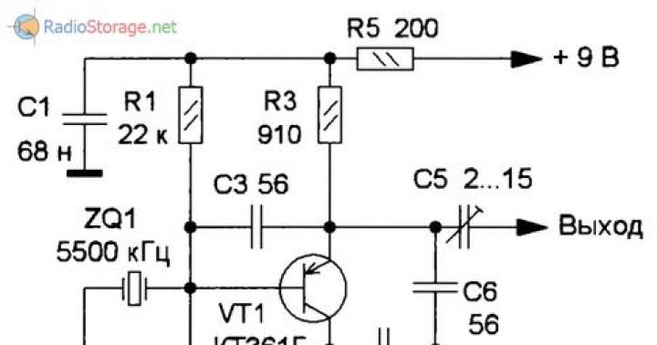
The key can control quartz telegraph local oscillators through the collector circuit (Fig. 2), source (Fig. 3) and emitter (Fig. 4). All three generators are made according to the capacitive three-point scheme.

Rice. 2. Diagram of a quartz telegraph local oscillator.

Rice. 3. Scheme of a quartz telegraph local oscillator (option 2).

Rice. 4. Scheme of a quartz telegraph local oscillator (option 3).
Trimmer capacitors included in the quartz resonator circuit provide tuning of the generation frequency, and the same capacitors installed at the output provide adjustment of the signal level supplied to subsequent stages.
Vladimir RUBTSOV (UN7BV), Astana, Kazakhstan. Radio 12-17.
Literature:
- Raudsepp X. Economic telegraph key. - Radio, 1986, No. 4, p. 17.
- Vasiliev V. Key on two microcircuits. - Radio, 1987, No. 9, p. 22, 23.
Format: txt, jpg files in rar archive.
Size: 111 kb.
For many years, radio amateurs have preferred to use automatic telegraph keys to transmit Morse code. Such an electronic device, controlled by a mechanical manipulator, provides a clearer transmission of Morse code characters with less stress on the operator's fingers. It also allows you to easily adjust the speed of transmission of characters of the telegraphic alphabet, without violating the accepted ratio of the duration of the sounding of dots and dashes (1: 3).
The published key worked for many years without failures and complaints. Has been collected since publication in Radio magazine.
It contains a clock generator on the elements DD1.1-DD1.3, a shaper of "dots" and "dashes" on D-flip-flops DD3.1, DD3.2, a pulse adder on the element DD2.4, a tone generator on the elements DD2.1, DD2.2 and transistor VT1, which serves for auditory control of the transmission of a telegram, an amateur radio transmitter control unit (transistor VT2 and electromagnetic relay K1) and a manipulator SA1 with element DD2.3.
How does such a telegraph key work? In the neutral position of the SA1 manipulator, when its armature does not touch the side contacts, the clock generator does not work, as it is blocked by a low-level voltage at the lower input of the DD1.1 element according to the circuit, connected to a common wire through a resistor R3 of relatively low resistance. The control tone generator is also blocked by a low-level voltage from the output of element DD2.4. This element is in the zero state because at this time the direct output of the trigger DD3.1 and the inverted output of the trigger DD3.2 has a high voltage. The operation of the telegraph key is illustrated by timing diagrams:

To form a “dash”, the armature of the SA1 manipulator touches the left (according to the diagram) contact. Element DD2.3 switches to a single state and a high-level output voltage starts the clock generator. From this moment on, the clock generator pulses appear at the output of the matching inverter DD1.4 (diagram a in Fig. 2), which are fed to the input C of the trigger DD3.1. The period of the pulse sequence of the clock generator, regulated by the variable resistor R1, is equal to the duration of the "point".
On the edge of the first pulse, the trigger DD3.1 switches to the opposite state, as a result of which a low-level voltage appears at its direct output, which translates the element DD2.4 into a single state. At the same time, the tone generator is turned on, since now a high-level voltage has appeared at the top input of the DD2.2 element. The audio frequency pulses are amplified by the transistor VT1, which is turned on by an emitter follower, and from the engine of the variable resistor R7, which is included in the emitter circuit of the transistor, the pulses are sent to the headphones BF1. At the same time, relay K1 will operate, contacts K1.1 of which manipulate the transmitter.
On the edge of the second pulse of the clock generator, the trigger DD3.1 switches to a single state and the voltage drop at the inverted output switches the trigger DD3.2 to the zero state (diagrams b and c in Fig. 2). Now, at the lower input of the DD2.4 element according to the circuit, there will be a low-level voltage, but the single state of this element will remain for the duration of the two “points” (diagram d in Fig. 2). Only on the front of the fourth pulse of the clock generator, when both triggers return to their original state, the DD2.4 element will go to the zero state and block the tone generator with a low-level output voltage. At the same moment, relay K1 will release the armature. There comes a pause, which is equal in duration to a “point”, the next cycle of sign formation begins. The duration of each "dash" is three times longer than the period of the "dot", which corresponds to the rules for transmitting the telegraphic alphabet.
To form "points", the armature of the manipulator SA1 is set to the right position. In this case, the DD2.3 element is again in a single state and starts the clock generator through the diode VD1. At the same time, a low-level voltage appears at the input R of the trigger DD3.2, as a result of which the trigger is locked in the zero state. The high-level voltage at the inverse output of this trigger will not prevent the pulses coming from the direct output of the trigger DD3.1 to act on the element DD2.4. At the output of this element, "dots" will be formed until the armature of the manipulator is set back to the neutral position.
What is the purpose of the diodes VD1-VD3? Diode VD1 is decoupling. When the DD2.3 element goes into a single state, a high-level voltage is supplied from its output through this diode to the lower input of the DD1.1 element, which starts the clock generator. This diode, in addition, prevents the low-level voltage from the DD2.3 element from entering the lower input of the DD1.1 element during those periods of time when the DD2.4 element is in a single state and the clock generator is in the generation mode with a high-level output voltage. Therefore, both "dots" and "dashes" will be formed completely, regardless of the moment the manipulator returns to the neutral position.
Diode VD2 also performs a decoupling function so that the low-level voltage at the output of element DD2.4 does not interfere with the operation of the clock generator.
Thanks to the VD3 diode, regardless of whether the armature of the manipulator is moved to the right or left position, the DD2.4 element will switch to a single state.
Due to the inclusion of the transistor VT1 by the emitter follower, the resistance of the headphones BF1 does not really matter. Resistor R8 limits the collector current of the transistor in the event of an inadvertent short circuit of the emitter of the transistor to a common wire.
Circuit board drawing of the electronic part of the automatic telegraph key:

All fixed resistors type MLT-0.25, oxide capacitor C1-K50-6. Electromagnetic relay K1-RES55 (passport RS4.569.724). Choke L1 is wound on a ring with a diameter of 8 and a height of 4 mm from 600NN ferrite; it should contain 150-200 turns of PELSHO 0.25 wire.
If the telegraph key is not yet supposed to be used to work with the radio station transmitter, then the entire transmitter control unit, starting with resistor R8, can be excluded. In this form, the device will help the successful development of high-speed listening and transmission of the telegraph alphabet.
Possible design of the automatic telegraph key manipulator:


The base 1 of the manipulator is two plates of strong insulating material (for example, textolite) folded together, fastened at the corners with screws 9, 10. Anchor 2 is a plate 115 ... 120 long and 15 ... fiberglass. It is fixed with screws 4 between two metal corner posts 3 and is held in a neutral position by rectangular shock absorbers 6 made of foam rubber glued to the base.
On the corner posts 7 made of steel or brass, reinforced on the base with countersunk screws, there are adjusting screws 8 that form the fixed contacts of the manipulator. Against them, on both sides of the armature, solder contacts from the contact plates of an unusable electromagnetic relay, for example, MKU-48 or the like. After setting the necessary clearances between the armature and the side contacts, the adjusting screws are fixed with nuts 11.
The conductors connecting the circuit board with the manipulator are soldered to petals 5 placed under the corner posts.
install and adjust telegraph key?
Firstly, you need to purchase or make yourself a reliable and convenient key with good contacts, with an easy move without play and with a handle in your hand.
It is desirable that the key rocker be rigid and long enough (14 ... 17 cm). For standard keys, the suspension of the rocker axle is usually on cores. The cores must be carefully adjusted and secured with locknuts so that there is no play, but the vertical movement must remain very light. The best suspension method is on precision miniature ball bearings. The spring should be stretched as little as possible, just enough so that the key just does not close itself. Wrenches that use a small magnet instead of a spring work well. The vertical stroke of the handle (head) of the key should first be about 1.5 ... 2 mm, and when the transmission rate is increased to 50 characters per minute, then it should be reduced to 1 ... 0.8 mm. The working contact should close clearly, without rattling, when the key head is pressed with a force of about 20 ... 30 g. Contacts should be cleaned regularly. This is usually done by stretching a strip of thick paper between them and at the same time pressing the head of the key.
Secondly, the installation location of the key must be very carefully selected so that during long-term work on the transmission the hand and the whole body do not get tired. Sit up straight at your desk with your shoulders back. The back is straight, rests comfortably on the back of the chair, and the right arm is bent at the elbow at a right angle - the shoulder part of the arm freely descends vertically along the side, and the forearm and hand are horizontal (as if they were lying on a comfortable armrest). The hand will most likely be approximately above the middle of the right edge of your right thigh. This will be the most convenient place where the key handle could best be located. The optimal place for attaching the key will, apparently, be below the surface of the table. If the height difference is small, then the key can be installed directly on the edge of the table.
If the table is high, then it is better to attach something like a shelf or console for a key under the table top. At the same time, there should be enough free space around the key head so that nothing hinders hand movements. In any case, it is necessary that the support is solid and completely stable, and the key is well attached to it (it can be convenient to use a screw clamp). Most likely, the installation location of the key will need to be repeatedly clarified during the training process, achieving the greatest convenience.
How to correctly transmit with a Morse key?
The head of the key is evenly covered with three fingers (thumb, index and middle) - not too hard, but tenaciously, without releasing it during the transfer process. The thumb and middle fingers cover the lower rounding of the head on the sides, the tip of the index finger is in the middle of the edge of the upper rounding of the head farthest from you. The ring finger and little finger should be slightly tucked into the palm of your hand. Elbow, forearm, wrist, hand and wrench must be in one straight horizontal line. (All this is much easier to do than it is to describe!)
In the initial position, the entire arm from the elbow to the hand should slightly pull the head of the key up, but should not be bent at the wrist joint. In the process of transmission, vertical movements must necessarily be carried out along the entire length of the arm from the elbow to the hand. The wrist should remain not tense, but elastic, and, slightly bending up and down within 3 ... 4 cm, play the role of only a shock absorber, but not a source of vibrations. Push-ups should be performed by the upward movement of the forearm, and not by the force of the key spring.


Neutral position
Pressing and squeezing must be carried out with fast, energetic movements, they must be accompanied by a clear and equal in strength knock of the working and opposite contacts.
How to train in transmission with a simple key?
Training begins with practicing the rhythm, transmitting several times for 40-90 seconds a continuous series of short and a series of long parcels (clicks), trying to maintain a stable pace and a 1:1 ratio of press/release durations in the first case, and 3:1 in the second. . If possible, it is good to do these exercises in time with the metronome. Then they proceed to the transmission of series from successively alternating short and long parcels, and only after that - to the transmission of Morse code signals.
In no case should you be in a hurry, attention should not be focused on speed, but above all on the rhythm and clarity of your transmission. The speed will come gradually, in the process of training. The duration of the sounding of short parcels ("dots") and pauses between parcels of the same character must be equal. Long parcels ("dashes") and pauses between letters should be three times, and the spaces between words should be five to seven times longer than "dots".
Before each workout, in order to “tune in” to the correct rhythm, it is useful to listen to a high-quality transmission (computer or tape audio recording) with obviously standard ratios of the duration of all elements of the Morse code exactly at the speed with which you yourself intend to transmit. From time to time, you can practice by passing the key in unison with the sound of a standard transmission (for this, of course, you need to prepare a printout of its text in advance).
For training, prepare appropriate texts in advance (based on 3-4 minutes of transmission each). It is best if they are printed or clearly handwritten in sufficiently large capital letters. Standard training radiograms (non-sense) usually consist of five-character groups, five groups per line, and are transmitted in the same order as normal text, i.e. line by line. The semantic text for training in the program is suitable from any newspaper or book with a large Latin font. From time to time, it is also a good idea to use tables of telegraph codes and abbreviations as texts for transmission - along the way they will be remembered.
If an error occurred during the transmission of the text, a series of at least seven "dots" should be transmitted and the entire word or group of characters should be repeated completely from the beginning.
After the transmission of each text (3-4 minutes), let the hand relax and rest for about a minute. Experienced radio operators are able to transmit key for hours almost without interruption, but this is achieved only by long training. The load should be increased very gradually. You should not exercise after hard physical work.
The quality of their transmission is controlled by ear by including any simple sound generator in the key circuit. You can also record the signals you transmit on a tape recorder, so that you can listen to them again, as if from the side. From time to time it is useful to monitor visually, using an oscilloscope with a sufficiently large afterglow and a slow (several seconds) sweep, the Y-input of which can be connected in parallel with the output of a sound generator or tape recorder. All deviations from the standard ratios of the duration of parcels and pauses will be clearly visible on the screen.
When sufficient automatism and consistently good quality are achieved, one should also start training in the transmission of words, phrases and code expressions without a written text - directly "from the head".
At the next stage, it is desirable to bring the transmission of standard amateur radio communications to automaticity - so that in the future, during real work on the air, you do not need to think about the simplest procedures every time.
What is a semi-automatic telegraph key?
Semi-automatic telegraph keys appeared at the end of the 19th century on wired communication lines. These were mechanical devices with a pendulum vibrator, which provided automatic transmission of a series of "dots", and "dashes" were usually formed in much the same way as on a simple Morse key - manually, separately.
The most popular model was developed and released by the American company "Vibroplex", therefore, in general, keys of this kind are often called vibroplexes. This company exists to this day and continues to successfully produce and sell all the same telegraph keys.
Since about the middle of the last century, the so-called electronic semi-automatic keys have become widely used. Such a key consists of a manipulator and an electronic unit. The manipulator is, in essence, a switch with two contacts that close when its handle is slightly deviated to the right and left from the neutral position. The electronic unit provides sequences of short or long bursts of a given duration in the output circuit when the right or left contacts of the manipulator are closed, respectively. It is usually based on a square wave clock and a simple logic circuit. This block also includes output circuits (relays) for controlling the transmitter and a sound generator for self-listening of the transmission.
Semi-automatic electronic key manipulator
Manipulators of electronic keys are very.
The handle can be single, common to both contacts, or double - from two halves arranged in parallel - each to close its contact. With a single handle, it can be more difficult to achieve precise operation of the manipulator - after pressing to one of the sides, returning to the neutral position, such a handle can deviate further by inertia and close the opposite contact.
In its most primitive form, it can be an elastic plate, for example, a piece of cloth from a hacksaw, attached at one end to a vertical stand on a horizontal base (plank), and at the other end having a small flat handle and a pair of contacts on both sides. In the same way, it is possible to build a fully functional dual manipulator in half an hour from improvised materials.
The requirements for the manipulator of a semi-automatic key are in many ways similar to the requirements for a simple Morse key - no backlash, good contacts and a very easy working move. The main difference is that the pressures are made in the horizontal plane alternately with the thumb and forefinger, and the physical effort here is much less.
Typical parameters of the manipulator (approximately):
1) handle dimensions:
- length: 30...50 mm (horizontally);
- width: 20...35 mm (vertically);
- thickness: single 4...8 mm, double 10...15 mm;
-height of the lower edge above the table surface: 7...15 mm;
2) horizontal travel (from neutral to contact in both directions): 0.6 ... 1.2 mm;
3) force required for contacting: 10...15 grams;
4) resistance to overloads with efforts applied to the handle in any direction, not less than 3 kgf;
5) handle material: ebonite or hardwood is best.
The manipulator must give the operator a clear tactile sense of the moments of contact. And, no less important, it should be just beautiful. After all, he will be in front of you all the time.
The electronic part of the key.
The electronic part of the key is usually designed as a structure separate from the manipulator. Often this node is built directly into the transmitter. In all cases, it is necessary that the speed control knob (clock generator operation period) be in a convenient place, since it is often necessary to change the speed right during the transmission. The standard ratio of durations of "dots" and "dashes" is 1:3. Some operators prefer that "dashes" be formed a little more stretched, up to 3.3 ... 3.5 times the duration of the "dot", but this is not rational at a high transmission rate. The duration of pauses between messages within each character should automatically be equal to the duration of the "dots". These ratios must be preserved in the signals emitted on the air, so sometimes it is necessary to correct the parameters of the transmitter manipulation circuits, achieving, in particular, the same delay time of the leading and trailing edges of radio pulses of telegraph parcels. Pauses between characters, equal in duration to one "dash", and between words - two "dashes", must be maintained by the operator himself. As needed, he can vary them during the transmission (you can pause a little more than the standard ones, but not less!).
It is impossible to transmit with an electronic key without simultaneously listening to the transmitted signals (that is, there must always be a feedback between the movements of the hand and the output signals of the key). Therefore, when developing an electronic circuit, it must be taken into account that at the beginning of the transmission of the next character, the self-listening tone signal should appear no later than 5 ... 7 milliseconds, counting from the moment the manipulator contacts first closed.
It is also good if the circuit provides the memorization of one pressing of each of the contacts, if it happened when the transmission of the message caused by the closing of the opposite one has not yet ended, and, at the end of the transmitted message, it issues after a standard pause a message corresponding to the "memorized" pressing (the so-called " point memory"). However, it is better to use this additional automation not from the very beginning of training, but at a later stage, when a transmission rate of more than 60-80 characters per minute has already been reliably achieved.
Where to install the semi-automatic key manipulator?
The key manipulator should be located exactly where it is convenient for the operator, and not vice versa. Sit at the table in the way that is convenient for you, place your right hand freely in front of you with your elbow and your entire forearm on the table. The hand should naturally lie on the table, the thumb and forefinger are slightly extended, and the rest are slightly tucked up to the palm. Set the manipulator on the table so that its handle falls in the middle between the ends of the thumb and forefinger. In the process of training, specify the most convenient place for installing the manipulator.
In any case, the table must be stable, and the manipulator must be securely fixed to its surface. Most often, they try to make the base of the manipulator massive (for example, from a steel or bronze plate weighing up to 1 ... .
How to work on a semi-automatic key?
Unlike working on a simple key, physical effort when working on a semi-automatic key is much less. The right hand (for lefties, respectively, the left) should lie completely free on the table with the entire forearm in a position that is convenient for you. Manipulation is not carried out with the whole hand, but only with the hand, mainly with the thumb and forefinger. The remaining fingers lie freely on the table, slightly bent under the palm. No need to hold the manipulator handle all the time. In the initial position, there may be a small gap between the fingers and the handle. The fingers should not be tense and begin to move a little "on a grand scale" only when you need to press in one direction or another.


By pressing in which direction should "points" be transmitted, and in which direction - "dashes"? In a mechanical semi-automatic device, a series of "dots" requires a sharp press with some force to actuate the pendulum vibrator, and the duration of each "dash" is entirely due to pressing the contact with another finger. Therefore, on the vibroplex, “dots” are usually betrayed by a stronger thumb, and “dashes” by the index finger. With an electronic key, the situation is different - the pressing forces in both directions are the same and small, and the index finger, as more mobile, is more suitable for transmitting short "dots". However, no one has yet proved or disproved the advantages or disadvantages of "right-hand" or "left-hand" movement, so when working on an electronic key, this does not matter and is only a matter of habit.
Once upon a time, some radio amateurs offered to transmit on a semi-automatic key with the left hand. They motivated their proposal by the fact that if there is always a pencil in the right hand, then it is possible to quickly move from transmission to recording the received, and vice versa. The proposal received some distribution about twenty-five years ago, but the expected effect was not confirmed by anyone. In practice, it is much more convenient to keep the left hand most of the time in the area where the main controls of the radio station are located (including the key speed controller), and the right hand to alternately record and transmit. Many of those who keep a hardware log are still on paper, not on a computer, and leave a pencil in their hand during transmission, not put it on the table. In general, this is also mainly a matter of habit. When one of the hands is well "trained" to transmit, then, if desired, it is easy to learn how to do it with the other. To do this, you have to reverse the connection of the manipulator contacts so that the "dots" and "dashes" are transmitted by the fingers of the same name of the other hand (hand movements are symmetrical).
The training methodology is the same as on a simple key, with the exception of the "warm-up" - the transfer of a long series of "dots" and "dashes" at the beginning of the training is not required here. You can immediately work out the transmission of individual letters and numbers at a low speed, moving from simple to complex, and when this is mastered, to the transmission of various texts.
What's happened " iambic key"?
An iambic keyer is an electronic key that differs from a conventional semi-automatic key only in that when both contacts of the manipulator are closed, it generates a series of successive short and long parcels at the output. Of course, the manipulator of such a key must be with a double handle and independently operating right and left contacts.
Thus, in order, for example, to transmit the letter C (Latin), the operator only needs to squeeze the manipulator handle with his fingers for the right time, that is, make only one movement instead of four, as in a conventional semiautomatic device. Economy of movements is also obtained on other signs, where "dots" and "dashes" are interspersed (for example, the letters P, Q, Y, X). However, the experience of the best high-speed radio operators did not reveal any noticeable difference in the results of adherents of iambic and conventional modes of operation.
Working on an iambic key is somewhat different from the usual one, so when moving from one to another, you have to relearn. Until considerable experience has been accumulated on a particular key, it is better not to change the transmission method. An iambic key can be used to transmit in the normal, "non-iambic" way, by using a single key or a dual key, but adjusted so that its opposite contacts cannot close at the same time.
E. KROCHAKEVICH, ( VQ 2 LE )
One example of the use of logic integrated circuits (ICs) in amateur radio practice is the automatic telegraph key offered to the attention of readers, which is distinguished by its small dimensions, high reliability and ease of use.
For its construction, both diode-transistor and transistor-transistor logic ICs of two types can be used: multi-input AND-NOT logic elements (gates) and front-clocked JK flip-flops.
Rice. 1. Schematic diagram of an automatic telegraph key
The schematic diagram of the key is shown in fig. 1. The device contains a clock pulse generator (GTI) built on gates D1.1 And D1.2 triggers D3 And D4, trigger control scheme on elements D1.S And D1.4, monitor assembled on valves D2.1D2.2 And D2.3 and the final stage based on the element D2.4 and transistors V7 And V8. Diagrams of voltages in the circuit, illustrating its operation, are shown in fig. 2.

Rice. 2. Plots of signals in the circuit
triggers D3 And D4 keys operate in counting mode and divide the frequency of clock pulses (Fig. 2, A), following with a period T, to 2. To the final stage, the signals from the outputs D3 And D4 come through the scheme D2.4 performing operation AND. Thus, the trigger D3 generates points and intervals of duration T(Fig. 2, b), and adding from the output D4 the signal shown in fig. 2, V, duration 2T ensures the formation of a dash, the duration of which will obviously be ZT. The summed signal (see Fig. 2, G) from the exit D2.4 enters the input of the final stage - to the base of the transistor V7.
In the process of transmission, the manipulator switches the inputs of the valves D1.3 And D1.4, at the same time to triggers from the outputs of elements D1.3 And D1.4 signals are received that allow them to switch. Link inverted trigger output D4 with valve inlet D1.3 needed to enable the trigger D3 in the counting mode when generating a dash signal, regardless of the position of the manipulator during the transmission of this character. An additional connection of the output of the GTI with the input J 4 of the trigger is also introduced into the scheme of the proposed key D4, excluding the possibility of simultaneous formation of signals C 3 = 0 and J 4 = 1, which would lead to the probability of a false transmission of a dash instead of a dot (the subscript of the name of the trigger input corresponds to the serial number of the trigger).
To evaluate the advantages of the automatic telegraph key circuit using front-timed JK flip-flops, it is essential that the JK flip-flop switches from zero to one without a long presence of one at input J. To change its state, at least a short coincidence in time of the signal is sufficient. J = 1 and the top of the clock pulse. Thus, the coincidence of signals J= 1 and C = 1 for subsequent J = 0 and WITH= 1 ensures the memory of the received control signal and, consequently, the memory of the position of the manipulator. In this case, clock pulses arrive with a duty cycle equal to 2 (the duration of the pause is equal to the duration of the pulse), and the position of the manipulator is stored here during that half of the interval between two characters of the message, which is directly adjacent to the beginning of the next character. Closing the manipulator in the time interval when C 3 = O will not have a response. Note that when transmitting a message at a low speed, when the actual duration of pressing the manipulator can be much shorter than the point (or interval) between the characters of the message, memory of the position of the manipulator is required throughout the interval to guarantee a reliable response to each closing of the manipulator. On the contrary, at high message rates, the actual duration of pressing the manipulator can be somewhat longer than a point. In this case, the memory of the position of the manipulator is not needed at all (at least in the entire interval), since if it is available, even the smallest overexposure of the manipulator will lead to the processing of an extra sign. Thus, the construction of the proposed key with the memory of the position of the manipulator exactly in the half of the interval between the characters of the message is a solution that, to a certain extent, simultaneously satisfies both of these conflicting requirements.
The GTI of the proposed key is built according to a simple scheme of a symmetrical multivibrator on valves D1.1 And D1.2 with timing capacitors C1 and C2. The clock frequency, and hence the message rate, is set by adjusting R3 depending on the desire or skill of the operator. When designing a switch, one should keep in mind the rather sharp dependence in such a GTI circuit of the generation frequency on the magnitude of the supply voltage. So, for example, when the adjustment position R3 corresponds to the maximum message transfer rate (engine R3 on the case), a change in the supply voltage by 1% causes a change in the frequency of the clock pulses by 3 - 5%. This circumstance imposes certain requirements on the stability of the power supply. In the process of adjusting the GTI, a breakdown or instability of generation is sometimes observed. The essence of this phenomenon is that with the simultaneous charge of capacitors C1 And C2 to the same voltage, the inputs of both gates of the multivibrator receive logical zero levels, and the outputs are logical one levels, and generation, therefore, is absent. If during the tuning process in the GTI such a disruption of generation occurs, you should turn off the power and discharge both capacitors. From the point of view of stable GTI generation, the supply voltage to the key circuit should be supplied with a sharp edge, for example, using a toggle switch. Diodes VI And V2 designed to protect valve inlets D1.1 And D1.2 from negative voltage half-waves formed during the recharging of capacitors C1 And G2. The absence of these diodes can lead to malfunctions of the key.
As already mentioned, in the device shown in Fig. 1, pulses with a duty cycle equal to 2 (meander) are formed at the GTI output, which provides memory for the position of the manipulator in half the interval between the message characters. Within this interval, the memory can be increased or decreased at will of the designer. To do this, it is enough to break the symmetry of the arms of the multivibrator by changing the capacitances of the capacitors C1 And C2.
The presence of a monitor key in the scheme, at least in the form of a layout, greatly simplifies the process of setting up the device, and the use of the monitor in the final design does not impair the overall reliability and noise immunity of the key, but it facilitates the operator's work.
In this case, the monitor is a low-frequency rectangular signal generator, assembled according to the multivibrator circuit on logic elements D2.1 And D2.2. The monitor also includes a key buffer stage on the valve D2.3. One high-impedance or a series of low-impedance headphones can be connected to the monitor input. The most effective use of the TM-2M microtelephone.
The output stage of the telegraph key can be built according to various circuit diagrams, both using transistors and microcircuits. On fig. 3 shows a variant of building the output stage of the key using K155 series microcircuits, and in fig. 4 and 5 - using transistors, for example KT315. Each of these options has its own advantages and disadvantages, which should be taken into account when designing. In particular, when building a transistor version of the output stage, relatively high voltages can be used to power it, limited only by the value of the maximum allowable collector-emitter voltage of the transistor used, hence the wide choice of relay types P1, rated operating currents of which should not exceed 100 mA (in relation to KT315 transistors). In addition, the mounting area occupied by two KT315 transistors is less than the area occupied by the microcircuit. When building an integrated version of the output stage, the relay and logic circuits must be powered by the same voltage, and the maximum output current limitation of each valve (15 - 30 mA) makes it difficult to select a relay with the appropriate voltage and actuation power levels. In addition, the design in this embodiment is loaded with a sufficiently large number of attachments. (R10 - R13 in fig. 3) to evenly distribute the load on each valve.


Rice. 3. Option to build the output stage of the key on logic microcircuits
Rice. 4. Option to build the output stage of the key on transistors (triggering of the relay closing P1)
Rice. 5. Option to build the output stage of the key on the transistor (triggering to open the relayP 1)
It is advisable to use microcircuits in the output stage of the key only in cases where all the operational automation of the radio station is made on logic elements with the same supply voltage (+ 5 V), and the power source has sufficient output power. The use of transistor stages shown in the diagrams of fig. 4 and 5 is justified in cases where, in order to reduce the number of microcircuits, the monitor and valve are excluded from the design D2.4. In other cases, it is advisable to build an end stage according to the scheme of Fig. 1.

Rice. 6. Schematic diagram of the GTI
Of particular interest is the use of a GTI as part of a telegraph key, the schematic diagram of which is shown in fig. 6. Here using a resistor R3 at the same time, the frequency and duty cycle of the clock pulses are adjusted. This allows, at low transmission rates, to work with the memory of the position of the manipulator in almost the entire interval between the characters of the message, thereby providing an unambiguous response of the key to any short-term closure of the manipulator. At the maximum speed of the key, the memory of the position of the manipulator in the interval between adjacent characters of the message is practically absent, which excludes the processing of extra characters of the message in case of possible overexposure of the manipulator. Note that in the middle of the speed control range, the memory of the position of the manipulator, as in the key diagram in Fig. 1 spans half the spacing between adjacent message characters.
The parameters of the attachments and the pin numbers of the microcircuits are indicated in the figures for the case of using ICs of the K155 or K136 series. as valves D1.1 - D1.4 And D2.1 - D2.4 you can use K155LAZ or K136LAZ, and as triggers D3 And D4- IC K155TV1 or K136TV1. Thus, the circuit is built on four integrated circuits. However, by excluding the monitor from the circuit and changing the construction of the output stage, three microcircuits can be dispensed with, and the use of ICs containing two JK flip-flops in one package, for example, K134TV14, reduces the number of microcircuits to two.
You can use any silicon or germanium small-sized diodes with low leakage currents, but microminiature diodes KD102 or KD104 with any letter indices are most successfully combined with microcircuits.
Some microcircuit inputs remain unused when building the key circuit. In the general case, to increase the noise immunity of the key, the unused inputs should be supplied with a logical unit voltage (+ 2.5 - b4 V), and also shunt the power outputs of each microcircuit at its installation site with a 0.1 μF capacitor. However, given the absence of Fig. 1 long lines that distribute powerful pulses with steep fronts, and sufficiently large actuation powers of elements of the K155 and K136 series, it is quite acceptable to leave unused inputs unconnected (such as installation inputs R and 5 triggers D3 And D4). Unused inputs J and K flip-flops can also be left unconnected, or unused inputs J can be combined with one of the enabled inputs J or output Q; and inputs TO- with the output of each flip-flop, especially since the inputs J of most integral JK flip-flops are located next to the output Q, and the inputs TO- with exit Q. This is decided in each case in the process of drawing up the wiring diagram. The unused inputs of the 2I-NOT gates are combined with the working ones. At the stage of prototyping and adjustment, however, it is not recommended to connect unused outputs; then, in case of failure of one of the working inputs, it will be possible to use the previously unused one.
To increase the overall noise immunity of the key in cases of insufficiently effectively shielded output stage of the transmitter or in the presence of other interference at the points of connection to the device of conductors from the potentiometer engine R3 and electrodes of the manipulator, if necessary, it is necessary to install decoupling capacitors Ср with a capacity of 0.022 - 0.068 μF. Diode V4 installed to protect the valve inlet D1.3 from pickups of positive polarity, which increases the noise immunity along the manipulation circuits. Capacitor C5 necessary to exclude the impact on the key circuit of switching interference that occurs during the operation of the relay PL Relay contacts P1 in the transmitter manipulation circuit, they are shunted by an RC circuit to eliminate their sparking, as well as to electrically neutralize the vibration of the contacts at the time of switching. This requirement is not specific due to the use of chips in the key design; however, it is important to keep it in mind, especially when trying to imitate the GTI action with a button, in order to check the action of the logical part of the key circuit. Capacitor C p with a capacity of 0.047 - 0.068 uF is connected to the power buses to prevent voltage surges at the moments of switching circuit elements during the operation of the key.
This electronic telegraph key is made using only two simple microcircuits K155LA3 and K155TM2. The circuit diagram is very simple.
A clock generator is assembled on the elements DD1.4 and DD1.1, the frequency of which can be controlled by a variable resistor R1. On element DD1.3, a generator start node is made. Trigger DD2.1 generates "dots", DD2.2 - "double dots".
When the manipulator is moved from the middle position to the “Points” position, a logical “0” is sent to pin 9 of the DD1.3 element. In this case, a logical "1" comes to the inputs of the DD1.4 element, and the clock generator begins to form a rectangular pulse.

At the inverse output of the trigger DD2.1, a low logic level immediately appears, which is fed through the diode VD1 to the generator start node. This allows you to form "dots" of the same duration, regardless of when the manipulator was returned to its original state. Pulses from the direct output of the trigger DD2.1 through the diode VD5 are fed to the transistor VT1 operating in the key mode. Relay K1 is included in its collector circuit, which switches the corresponding transmitter circuits.
When the manipulator is moved to the “Dash” position, a low logic level is applied to pin 9 of the DD1.3 element and pin 5 of the DD1 2 element. This starts the clock generator. From the inverse output of the trigger DD2.1. and also from DD2.2 through the diodes VD1, VD3, VU4, the elements DD1.3 and DD1.2 receive a logical "0", which ensures the operation of the clock generator at the time of the formation of a "dash" of normal duration. "Dash" is obtained by summing on the resistor R3 "dots" and "double dots" coming from the direct outputs of the triggers DD2.1 and DD2.2 through the diodes VD5 and VD6.
Details of the electronic key are placed on a printed circuit board measuring 65x45 mm.


In the key, you can use microcircuits of the K133, K158, K130 series. Diodes VD1-VD6 - any pulse, transistor VT1 - any low-power n-p-n structure. Relay K1 - RES-15 (passport RS4.591.002). Instead, you can use RES-43 (passport RS4.569.201) or others in which the response voltage does not exceed 5 V.
You can download other schemes and solutions for telegraph keys