Switching power supply on IR2151-IR2153
The advantage of any switching power supply is that it does not require winding or buying a bulky transformer. And only a transformer with a few turns is required. This power unit do it yourself It's easy and requires few details. And the basis is that power supply on the chip IR2151
A characteristic feature of this power supply is its simplicity and repeatability. The circuit contains a small number of components and has performed well for more than two years. A typical step-down transformer from a computer power supply is used as a pulse transformer.

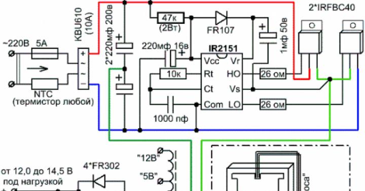
There is a PTC thermistor at the input.– a semiconductor resistor with a positive temperature coefficient, which increases its resistance sharply when a certain characteristic temperature TRef is exceeded. Protects the power switches at the moment of switching on while charging the capacitors.
Diode bridge at the input to rectify the mains voltage to a current of 10A. Used diode assembly type "vertical", but you can use the diode assembly type "stool".
A pair of capacitors at the input is taken at the rate of 1 microfarad per 1 W. In our case, the capacitors will "pull" the load of 220W.
Extinguishing resistance in the power supply circuit of the driver with a power of 2 W. Preference is given to domestic resistors of the MLT-2 type.
Driver IR2151- to control the gates of field-effect transistors operating under voltage up to 600V. Possible replacement for IR2152, IR2153. If the name contains the index "D", for example IR2153D, then the FR107 diode in the driver harness is not needed. The driver alternately opens the gates of field-effect transistors with a frequency set by the elements on the legs Rt and Ct.
FETs are preferably used by IR. Choose for a voltage of at least 400V and with minimal open resistance. The lower the resistance, the lower the heat and the higher the efficiency. You can recommend the IRF740, IRF840, etc. The IR FET Handbook in Russian can be downloaded here. Attention! Do not short-circuit the flanges of the field-effect transistors; when mounting on a radiator, use insulating gaskets and bushing washers.
A typical step-down transformer from a computer power supply. As a rule, the pinout corresponds to that shown in the diagram. Homemade transformers wound on ferrite tori also work in this circuit. The calculation of home-made transformers is carried out at a conversion frequency of 100 kHz and half of the rectified voltage (310/2 = 155V).
When choosing a transformer, you should take one that has shorted outputs on the native board as shown in the diagram. It is important. Otherwise, you should close as it is done on the board from which you are dismantling the transformer.
Diodes at the output with a recovery time of no more than 100 ns. Diodes from the HER (High Efficiency Rectifier) family meet these requirements. Not to be confused with Schottky diodes.
The output capacitance is the buffer capacitance.Do not install a capacitance of more than 10,000 microfarads.
Printed circuit board
 Practice has shown that this application does not require a special organization of feedback, inductive power filters, snubbers and other "bells and whistles" inherent in pulse converters. One way or another, the typical defects characteristic of "poor nutrition" (background and extraneous sounds) are not felt in the sound by ear.
In operation, field-effect transistors do not heat up much.
Passive cooling is enough for them. IR FETs are very resistant to thermal degradation and operate up to 150°C. But this does not mean that they should be operated in such a critical mode. For such cases, it will be necessary to organize active cooling, and in a simple way, install a fan.
Like any device, this power supply requires careful and accurate assembly, correct installation of polar elements and caution when working with mains voltage. When this power supply is turned OFF, no dangerous voltage remains in its circuits. A properly assembled power supply does not need to be configured and adjusted.
When assembling some next device, the question of how to power it is more and more tormenting. Yes, it’s good when there are a lot of different equipment where there are suitable transformers, and if you rewind ??? Rewinding a transformer is not a pleasant task, even if applications for calculating a transformer help in calculations, the rewinding process itself is often annoying.
I remember how it was TSSh-180, a good anode-filament trance, and I had to rewind. I probably wound it for two days, plus shed it with varnish so that the insulation would be better and not buzz ... I collected it, such a healthy one. Himself weighing 3 kg and almost fell on his leg. I thought about it all and decided to switch to switching power supplies and there are a lot of reasons for this.
Reasons for choosing switching power supplies:
1. P The first and not unimportant reason is financial. Here we have the same TSSh-180 a.-incandescent costs 150-180 UAH. While the assembled SMPS 200W on IR2153 will cost 130-160 UAH. Yes, the difference is not great, but your house is full of the necessary details. For example, I bought only IRF740 and IR2153 and paid 40 UAH. How's the difference?? And I also got rid of the trash a little)) And it’s also unforgettable that the bridge and the banks are already in the calculation, and you also need to buy this for the trance. And good jars about how well they cost. And on the SMPS instead of 22,000mF, you can put 3300mF and you won’t even notice the difference in filtering
2. In The second reason is the size. The trances are heavy, so 200 watts weighing 3-4 kg, it is replaced by an SMPS with a mass of 300 g and a board size of about 120 * 120 mm. It is convenient to assemble something powerful in a DVD box, for example Lanzar ...
3. E then a low level of interference in the range of 20-20,000 Hz. This is very good for a low-frequency amplifier, even excellent. No interference, no background.
On the diagram we see the power part in which there is: protective circuits (R1, R2, FU1) filter C-R-C (C1, L1, C1), rectifier with filter divider (VD1 (400V 3A), C3, C4, C6, C7, R44, R6) and a key part which includes two mosfets (VT1, VT2), a transformer (T1) and two noise suppression circuits (R8C9, C8R7)
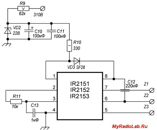
Nothing complicated in the control part. The supply part of the microcircuit consists of a ballast resistor R9, a zener diode VD2. filter C10C11, and another ballast resistor R10. In the course of work, you may have to pick up R9R10.
The PWM frequency is set by R11C13. And it is calculated according to the formula f = 1 / 1.4 * (R11 + 75 Ohm) * C13. In our case f=1/1.4*(10000+75)*0.000000001=70896 Hz= 70.9 kHz. Be careful with toes

Well, there really is nothing to tell: Dual diode VD4, filter-rectifier C14-L3-C15-C16 and that's it. Remember when calculating that this is not a stabilized PSU and the voltage can float. Therefore, it is better to enter a couple of volts less when calculating
The application for calculating the pulse transformers will help you with the calculation of the transformer. Advice to wind the secondary with a scythe of a thinner wire in order to avoid the skin effect.
By the way, one of my friends from such a circuit is powered by 2.1 assembled on a TDA2030A with a total power of 65W. This is a small part of what the SMPS produces on the IR2153, but it has been working for a year. Yes, again, a 70W transformer right now costs the same as the SMPS unit on IR2153, so the SMPS also has a reserve of 130W ...
That's all, thank you all for your attention and good luck with the assembly ...
The power supply is built on a floor-bridge circuit based on the IR2153 chip. At the output of this block, you can get any voltage you need, it all depends on the parameters of the secondary winding of the transformer.
Let's take a closer look at the switching power supply circuit.
The power of the power supply with just such components is about 150 watts.
Mains alternating voltage through a fuse and a thermistor is supplied to the diode rectifier.
After the rectifier, there is an electrolytic capacitor, which, at the moment the unit is connected to the network, will be charged with a large current, the thermistor just limits this current. A capacitor is needed with a voltage of 400-450 volts. Further, a constant voltage is supplied to the power switches. At the same time, power is supplied to the IR2153 chip through a limiting resistor and a rectifier diode.
You need a powerful resistor, at least 2 watts, it is better to take a 5-watt one. The supply voltage for the microcircuit is additionally smoothed out by a small electrolytic capacitor with a capacity of 100 to 470 microfarads, preferably 35 volts. The microcircuit begins to generate a sequence of rectangular pulses, the frequency of which depends on the value of the components of the timing circuit, in my case, the frequency is in the region of 45 kHz.
A rectifier with a midpoint is installed at the output. Rectifier in the form of a diode assembly in the TO-220 package. If the output voltage is planned within 40 volts, then diode assemblies soldered from computer power supplies can be used.
The voltage boost capacitor is designed for the correct operation of the upper field switch, the capacitance depends on which transistor is used, but on average 1 uF is enough for most cases.
Before starting, you need to check the operation of the generator. For these purposes, about 15 volts of direct voltage is supplied from an external power source to the indicated pins of the microcircuit.
Next, the presence of rectangular pulses on the gate of the field keys is checked, the pulses must be completely identical, of the same frequency and filling.
The first start-up of the power supply must be done through a 220-volt safety incandescent lamp with a power of about 40 watts, be extremely careful not to touch the board during operation, after disconnecting the unit from the mains, wait a few minutes until the high-voltage capacitor is discharged through the appropriate resistor.
It is very important to point out that this circuit does not have short circuit protection, therefore any short circuits, even short ones, will lead to the failure of the power switches and the IR2153 chip, so be careful.
Simplified bridge on IR2153- such a device as a bridge implemented on a universal driver for controlling field-effect transistors is rightly considered one of the most effective converter modules. But, in order to assemble such a device, significant financial investments will be required, and the technological level of complexity in its manufacture must also be taken into account. That is, if you are going to take on the design of a high-power bridge for several kilowatts, then yes, there will be some difficulties.
But if you use the diagram below, then there will be no problems, especially since the device is assembled on two popular IR2153 chips, which are high-voltage drivers with an internal generator. The principle of turning on microcircuits is common and has been repeatedly tested on a half-bridge. The feature causes the priority clocking of the second microcircuit from the R-input.
Rated values of electronic components:
B1 - diode bridge RS2007, RS3507 and the like. When operating at capacities of more than a couple of hundred watts, it is necessary to put a radiator on it.
C1, C7 - electrolytes 630 ... 1000uF x 400V
R1, R5 - 33..56kOhm 2W. For a more accurate calculation, you can use the formula
R=310/(2*Cshutter*15.6*fwork+0.003)
C2, C5 - electrolytes 220uF 25V
C8, C9 - ceramic 0.1uF 25V
R8 - 2Ω 0.25W
R9 - 24kOhm
R10 - 6 kOhm
R2, C3 - calculated according to the datasheet on IR2153 based on the required frequency
IC1, IC2 - IR2153, IR2153D, IR21531 (if IR2153D is used, then do not set D1 and D2!)
D1, D2, D3, D4 - UF4007, BYW26C, BY329 or other similar ultra fast diodes
C4, C6 - tantalum 22uF 25V
R3, R4, R6, R7 - 10 ... 30 Ohm 0.25W (lower value for heavy gates, higher for light ones)
Q1, Q2, Q3, Q4 - IRF840 or something similar. It all depends on your needs
As for calculations, for example: R2, C3, as mentioned above, must be determined by the datasheet, in addition, there are many programs for calculating. If for someone this is a dense forest, then I think, then there is no need to undertake design at all.
The printed circuit board is shown below with the designations of the parts and their installation locations printed on it.
The load of this bridge can be a horizontal TV output transformer, an SSTC coil, or something similar, but the power should not exceed 1000 watts. If you use high power, then there is no guarantee in the stable operation of the microcircuit. If, nevertheless, there is a need to realize high powers, then it is necessary to add the capacitance of capacitors in the 310v filter circuit, then there is a possibility that it will work fine at high power.
Technical information
1.
When the start is carried out, a strong pulsed surge of current is created as a result of the ongoing charging cycle of the capacitors in the filter circuit. In this case, the automatic machines may trip, if this happens, then you need to install an NTC thermistor in the network circuit, which is used to protect pulsed power supplies and electronic ballast systems, having previously selected its values for the required current.
2.
When connected to the bridge as a load, the output line transformer, then the primary winding must be wound in the amount of 65 turns at least.
3.
When arranging elements on a printed circuit board, it is best to install panels under the microcircuits, and place the microcircuit itself in them after the circuit is fully assembled.
But not one, but four at once. In this material, you will be presented with several switching power supply circuits made on the popular and reliable IR2153 chip. All of these projects were developed by famous user Nem0. Therefore, I will write here on his behalf. All the schematic solutions shown here were personally assembled and tested by the author a couple of years ago.
In general, let's start with the so-called "high-voltage" power supply:
The circuit is the traditional one that Nem0 uses in most of its impulse designs. The driver receives power directly from the mains through the resistance. This, in turn, helps to reduce the power dissipated on this resistance, compared with the voltage supply from the 310v circuit. Switching power supply circuit has a function of smooth voltage switching, which significantly limits the starting current. The soft start module is powered through capacitor C2, which lowers the mains voltage 230v.
The power supply provides effective protection to prevent short circuits and peak loads in the secondary power path. The role of the current sensor is performed by a constant resistor R11, and the protection operation current is adjusted using the trimmer R10. During the cutoff of the current by the protection, the LED starts to glow, signaling that the protection has worked. The output bipolar rectified voltage is +/-70v.
The transformer is made with one primary winding, consisting of fifty turns, and 4 secondary windings, contain twenty-three turns. The diameter of the copper core and the magnetic core of the transformer are calculated depending on the specified power of a specific power supply.
Now consider the following power supply:
This version of the power supply is very similar to the circuit described above, although it has a significant difference. The fact is that here the supply voltage to the driver comes from a special transformer winding, through a ballast resistor. All other components in the design are almost the same.
The output power of this power supply is determined both by the characteristics of the transformer and the parameters of the IR2153 chip, but also by the resource of the diodes in the rectifier. In this circuit, KD213A diodes were used, which have a maximum reverse voltage of 200v and a direct maximum current of 10A. To ensure the correct operation of the diodes at high currents, they must be installed on a radiator.
The T2 choke deserves special attention. It is wound on a joint annular magnetic circuit; if necessary, another core can be used. Winding is done with an enamel wire with a cross section calculated according to the current in the load. Also, the power of the pulse transformer is determined depending on what output power you want to get. It is very convenient to make transformer calculations using special computer calculators.
Now the third circuit of a switching power supply on powerful IRFP460 field-effect transistors:
This version of the circuit already has a specific difference relative to previous models. The main differences are that the short circuit and overload protection system is assembled here using a current transformer. And there is one more difference, this is the presence in the circuit of a pair of pre-output transistors BD140. It is these transistors that make it possible to cut off the large input capacitance of powerful field switches, relative to the output of the driver.
There is still a small difference, this is a voltage-quenching resistor related to the soft start module, it is installed in the 230v circuit. In the previous diagram, it is located in the power path + 310v. In addition, the circuit has a surge suppressor that serves to dampen the residual pulse of the transformer. In all other respects, this one no longer has any differences between the above schemes.