Finally, there is an opportunity to show you a video on a topic that interests so many Internet users. In this video tutorial we will show you how to make a fairly powerful electric generator from a bicycle that will generate current of 12 and 220 volts. Thanks to this device, you can charge the battery in 1-1.5 hours and, through an inverter, power your TV or other electrical appliances for several hours. As a bonus, such a generator becomes a good exercise bike, which is pleasant to “ride”, realizing the benefits it brings. You can use a bicycle generator in the countryside, at home when the lights are often turned off, and on a hike it will be an excellent help for creating almost urban comfort if all the design parts are foldable and sufficiently mobile.
Technical characteristics of the bicycle generator. During a leisurely “ride”, rotation of the pedals generates an electric current of 5 Amperes, a voltage of 220 Volts. Rotation acceleration produces more than 10 Amps; In this mode, the author of this device blew a fuse.
To work you will need:
– 12 volt commutator motor;
– attachment to the motor axis – drill chuck;
– uninterruptible power supply or inverter from 12 to 220;
– 10 ampere diode: D214, D242, D215, D232, KD203, etc.;
– wires;
- bike;
– 12 volt battery (the higher the power, the longer its charge will last).
Assembly.
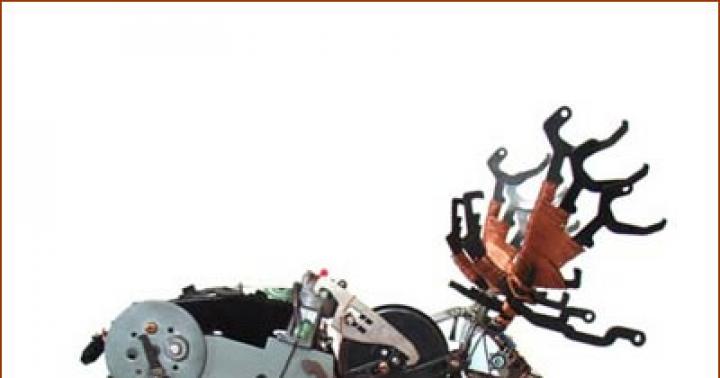
First, install the bike so that the rear wheel is suspended above the ground and rotates freely. To secure the bicycle in the desired position, the author of the video tutorial used available materials and made a stand from boards. He attached a drill chuck to the motor axle and installed the motor so that, with the help of a spring, it was securely pressed against the rear wheel. The connection turned out to be reliable, without slipping.

In this design, the motor acts as a generator, so you can use any 12-volt brushed motor. The more power the motor has, the more energy it will produce. The device made by the author uses a fan from a VAZ car. Its rated power is 120 W.
In order to find out how much power this motor is capable of generating electricity in generator mode, we connect a 90-watt light bulb to it and see that the generator’s performance is so high that the light bulb can burn out when the engine speed increases.
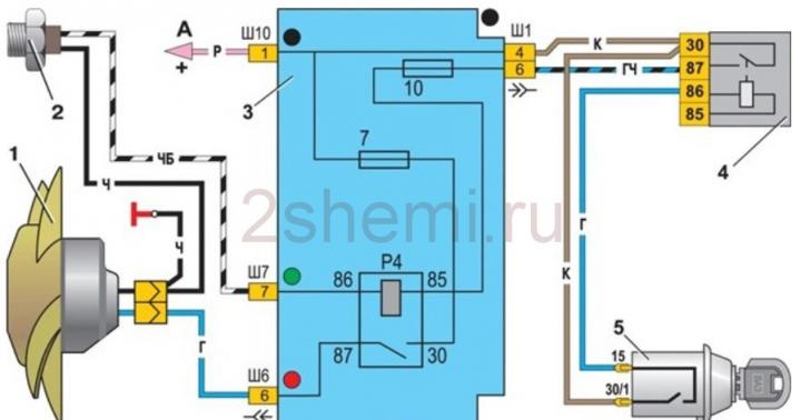
It is advisable to use a battery to store electricity. A car battery is good for this purpose. To prevent the motor from starting to rotate from the battery, you need to assemble a circuit with a diode that will cut off the current in the desired direction and prevent unnecessary discharge. The anode of the diode is to the plus of the engine, the cathode is to the plus of the battery.
Now you can charge a 12-volt battery, the voltage from which can be removed for equipment with the appropriate voltage. But in order for the voltage at the generator output to be 220 volts, an uninterruptible power supply from a computer will help.
The uninterruptible power supply design has a small 12-volt low-power battery. When the current in the network is turned off, the converter, which is included in the UPS circuit, increases 12 volts to 220, allowing the computer to operate on it for some time. In order to ensure operation for a long time, you can remove the low-power battery from the circuit and connect instead, as described above, a powerful car battery.
Now, by simply rotating the pedals, you can get 220 volts, almost the same as in a regular network. Such a generator can power many electrical appliances in the house. There is one thing. If you connect a load of more than 500 watts to an uninterruptible power supply, it starts to heat up and the battery quickly discharges. Therefore, it is necessary to compare the power of the bicycle generator and the battery built into it and the expected load. Instead of an uninterruptible power supply, you can use a car inverter from 12 volts to 220 volts.
When charging the battery by pedaling, the voltage on it will increase. When it reaches 14.4 Volts, the battery will be charged. You cannot continue charging further, since the electrolyte will begin to boil away when overcharging.
Unlike a gasoline generator, a bicycle-based electric generator does not require resources that may be in short supply.
Greetings, brainwashes! Homemade This brain guide has an excellent property - it allows you to combine business with pleasure, namely, by playing sports and generating electricity.
The basis homemade products- a bicycle connected to an engine, which will convert your calories into electric current. And in more detail, the rotation of the pedals is transmitted to the rear wheel, which accordingly rotates the engine shaft, as a result of which an electric current arises in the engine windings, which is supplied through the charge controller to the connected battery and “canned” there. An inverter is connected to the battery, having two socket outlets and two USB outputs. To control and monitor all electronics, an Arduino microcontroller is used, which turns on/off the charge controller and inverter, and also displays parameters from the sensors via an LCD display.
Materials and components:
Bicycle frame with rear wheel
Lumber and bolts (for stand)
Bicycle training stand
Motor 24V
Cooling system belt
Belt pulley
Battery 12V
DC-DC charger
DC-AC inverter with USB outputs and sockets
Arduino (I used Leonardo, but others will work)
MOSFET (Insulated Gate Field Effect Transistor)
LED and photodiode
Hall effect sensor
LCD screen
Toggle switch “On/Off”
Relay, 5V voltage regulator, diode, buttons and resistors
Step 1: Stand


To begin, we build a front fork stand from a piece of 60x180cm plywood, 5x10cm bars and studs with nuts. I made it because I got the bike without a front wheel and had to figure out how to fix it. Stand crafts It turned out to be functional and can withstand the pressure of even the most zealous “racers”.
You can also make some kind of stand for the rear wheel, but I came to the conclusion that a bicycle stand is the most suitable option. You just need to remove the additional load on the wheel, which sometimes happens on these stands, since it will only interfere with generation.
As a generator, you can take a 24-volt motor from a scooter, which we will force not to “eat” electricity, but to generate it. We remove the tire with the camera from the rim of the rear wheel and put on a belt from the cooling system, from which we take a pulley, which we install accordingly on the motor shaft. After that, we put the belt on the pulley and tighten it, then we fix the motor in this position on the plywood base.
The design of the stand is such that it can be adjusted, and this option allows you to tighten the belt and also remove the bike if necessary.
Step 2: From Alternator to Battery


Almost any rechargeable battery can be used as a “storage”; for example, I took a 12V lead-acid battery because it was on hand. But in any case, you need to know the technical characteristics and operating conditions of the selected battery for proper charge/discharge, which can be found in the technical data sheet. In my case, the battery does not “like” when the voltage rises above 14V and the current is not higher than 5.4A.
Completely discharging or overloading the battery can damage it or reduce its service life, so brain circuit an “On/Off” toggle switch is installed, which prevents current leakage under phantom loads, and an Arduino microcontroller is installed, which displays the state of the circuit.
Naturally, you cannot directly connect the battery to the motor terminals, this will simply “kill” the battery, so we install a charge controller between them, which will supply the battery with electricity of the current and voltage that it requires. The controller itself will turn on when you start pedaling homemade products, and holding the controller's start button for 3 seconds will check the battery status, and if it needs charging, it will begin. When you stop pedaling, the controller turns off.
When buying a charge controller, the main thing is to choose the necessary characteristics, that is, so that it operates in the same ranges as the generator and battery. So for my brain games You need a controller that can accept input voltage up to 24V and provide 14V with a current of no more than 5.4A. Basically, controllers have the ability to customize parameters, so I just set the current on it to 5A, as required for my brain accumulator.
Step 3: Inverter


You can’t simply connect your gadgets to a battery to charge, since this also requires a certain voltage and current, so we connect an inverter to the battery, which produces electricity with the parameters necessary for charging through its sockets and USB outputs.
Inverter for crafts should be purchased according to the battery parameters and calculated power. So the battery produces 12V, the power for charging a phone is approximately 5W, and a laptop is 45-60W. I selected an inverter with a power of 400W, 2 sockets and 2 USB outputs, although I do not plan to simultaneously charge gadgets at 400W.
You don't have to install an inverter if you plan to charge only your phone or other USB devices. Then you just need to lower the voltage from the battery to 5V and “output” it via a USB cable. With this method, electricity is not once again converted from DC to AC, and then from AC to DC, but many are still inclined to trust an inverter than an improvised USB port.
The inverter itself is connected simply: the positive input of the inverter to the positive terminal of the battery, the negative brainwalk to the negative terminal. And everything works simply: the motor charges the battery through the charge controller, the battery “powers” the inverter, and it charges the connected gadgets.
Step 4: Arduino and Battery Charge


It was already said earlier that in order for the battery to start charging, you need to hold down the start button of the charge controller for 3 seconds. This is a little inconvenient, it’s especially troublesome to explain the switching order homemade products to other people. Therefore, we will “hack” the charge controller and ensure that a simple press of a button starts the entire system and you can simply turn the pedals.
The charge controller is a “magic” box, on one side of which the positive and negative contacts from the battery are connected, and on the other side the wires from the motor are connected. Anything "between these parties" is beyond this brain guides, but still you have to open this box and touch the “magic”.
The buttons are connected to the circuit with a 5-track cable, and when one of the buttons is pressed, the signal from the fifth track passes through this button along the track connected to it to the board. We replace this 5-track cable with a bunch of five ordinary wires, that is, we unsolder the cable and solder five wires, on the other end of which we install a connector through which we connect the breadboard. On this breadboard we place 4 buttons, which are not yet connected to the microcontroller; we will control the charge controller.
IMPORTANT!!! If you decide, like me, to leave the controller board without a housing, then be sure to organize a heat sink, since during “intense” driving the controller gets very hot.
To “teach” Arduino to press the start button you need to use brain relay, which, based on a signal from the microcontroller, will withstand a 3-second “press” and turn on the controller. And although many relays have built-in diodes for protection, I still recommend installing an additional one to avoid current leakage back to the Arduino pins.
The question arises: when should the Arduino trigger signal? The answer is obvious - when you start pedaling, otherwise there is no point in starting the controller. The charge controller will not “charge” an already full battery, but you can once again not check the charge level manually, but shift this responsibility to the microcontroller, that is, make it monitor the voltage and current parameters. To do this, you can use the Arduino analog inputs, but they operate in the range from 0 to 5V, while the battery terminals are 11-14V, and the motor outputs are from 0 to 24V, so we can use voltage dividers. When connecting the battery to divide the voltage, we take one 1 kOhm resistor, and the second one, going to ground, 2.2 kOhm. Then, with a maximum voltage of 14V from the battery, the second resistor from which the reading will take place will be about 4.4V (more details in the article on dividers). When connecting the motor, we use 1kOhm and 4.7kOhm resistors in the voltage divider, then at 24V from the generator the Arduino will read as 4.2V. All these measurements in the Arduino code are easy to convert into actual values.
To prevent battery overcharging homemade products the voltage at its terminals should be less than 14V, but for the generator the parameters are more flexible - if the cyclist “generates” a voltage sufficient to turn on the controller, then the controller can charge the battery. As a result, the voltage parameters will be as follows: from the generator more than 5V, and for the battery less than 14V.
The microcontroller itself will be turned on via a “button” or something similar, since it is not reasonable to keep it turned on all the time. And it is better to “power” it not from a replaceable 9V battery, but from a 12V battery. To do this, we connect the microcontroller through a connector and a 5V voltage regulator to the battery, although Arduino supports a 12V supply voltage. By the way, you can power some other electronics from these 5V, rather than using the 5V pin on the Arduino for this. We must place the regulator on the radiator, since it gets very hot during operation.
Sample code:
// complete code at the end of this Instructable
int motor = A0; //motor/generator pin on the Arduino
int batt = A1; //12V battery pin
int cc = 8; //charge controller pin
int wait = 500; //delay in milliseconds
float afactor = 1023.0; //Arduino's analog read max value
float motorV, battV; //motor voltage and battery voltage
boolean hasBeenOn = false; //to remember if the charge controller has been turned on
pinMode(motor, INPUT);
pinMode(batt, INPUT);
pinMode(cc, OUTPUT);
motorV = getmotorV(); //motovr/generator output voltage
if (motorV > 1.0 && !hasBeenOn) ( //if our DC motor gives out more than 1V, we say it’s on
digitalWrite(cc, HIGH); //the cc pin is connected to a relay
//that acts as the “Start” button for the charge controller
delay(3500); //our charge controller requires the start button to be held for 3 seconds
digitalWrite(cc, LOW); //electrically releasing the start button
hasBeenOn = true; //the charge controller should be charging the battery now
delay(wait); //we want our Arduino to wait so not to check every few millisec
else if(motorV > 1.0 && hasBeenOn)(
delay(wait); //again, we don’t want the Arduino to check every few millisec
hasBeenOn = false; //the person is no longer biking
//we wrote separate functions so we could organize our code
float getmotorV())(
return (float(analogRead(motor)) / afactor * 5.0); //the motor gives out about a max of 5V
float getbattV())(
return (float(analogRead(batt)) / afactor * 14.0); //the battery technically is~13.5V
Step 5: Arduino and Inverter

Keeping the inverter constantly connected to the battery is not beneficial for several reasons. First, the phantom load discharges brain accumulator, and secondly, you need to make “protection” from cunning people who want to recharge the gadget, but do not want to turn the pedals to do so. Therefore, we again use Arduino, which will turn on/off the inverter and thereby control the charging outputs, without relying on the honesty and technical knowledge of the users.
Integrate the inverter and Arduino as a key for it, using a MOSFET. This is essentially an ordinary transistor, but it requires small gate currents, with large passing ones (but the gate voltage must be greater than that of conventional transistors, although this is not a problem for Arduino).
We connect the MOSFET in the circuit so that the negative output of the inverter is connected to the collector, the negative output of the battery to the emitter, and the output of the Arduino to the base. When all the required parameters match (such as driving duration, applied voltage, etc.), the Arduino sends a signal to the transistor and it opens, allowing current to flow from the battery to the inverter; if the Arduino interrupts the signal, the transistor turns off, breaking the circuit, and the inverter turns off.
I note that when large currents pass through the transistor crafts it gets very hot, therefore, just like on the voltage regulator, installing a heatsink on the transistor is mandatory!
Sample code:
//the bolded code
int mosfet = 7; // used to turn on the inverter
unsigned long timeOn, timecheck; // for time checking
if (motorV > 1.0 && !hasBeenOn) (
timeOn = millis();
inverterControl();
// the separate function
void inverterControl() (
battV = getbattV(); //check the battery voltage
timecheck = millis() - timeOn; //check how long the user has been biking
/* We want the user to have biked for a certain amount of time
before allowing the user to charge the user’s electronics.
We also need to be sure that the battery isn’t undercharged.
if (hasBeenOn && (battV > 10.0) && (timecheck > 5000) && !mosfetOn) (
digitalWrite(mosfet, HIGH); //the inverter is on when the Arduino turns on the MOSFET
mosfetOn = true;
else if ((battV<= 10.0)) { //turns off inverter if the battery is too low
digitalWrite(mosfet, LOW);
mosfetOn = false;
else if(timecheck<5000) { //turns off if the user stopped/hasn’t biked long enough
digitalWrite(mosfet, LOW);
mosfetOn = false;
Step 6: Arduino and Feedback


As feedback during training, you can take the values of the rotation speed of the rear wheel, that is, the “cyclist” will not only charge the battery, but also receive information about the intensity of his workout. To count the revolutions of the rear wheel, you can use an optical sensor and a Hall sensor.
Optical sensor
In his brain work I went by installing an optical sensor to read the number of revolutions of the rear wheel, and made this sensor from parts that came to hand. The idea is simple: an opaque object is attached to the wheel rim, here thin painted plastic, which, when rotated, periodically interrupts the LED-photodiode beam. The photodiode and LED themselves are installed in a piece of foam with a selected cavity in which the wheel rotates (see photo). Due to the flexibility of the foam, it is easy to place and configure the LED-photodiode system in it, namely, placing them on the same line, this is important, since photodiodes are very sensitive to the angle of the incident beam. As a result, when the plastic rotates, it should not interfere with the rotation of the rim itself and interrupt the beam.
The diode connection diagram is also simple: both diodes are supplied with 5V from the microcontroller, but it is necessary to install a resistor in the LED circuit, since the LED has low resistance and this means the current flowing through it will be large and the LED will simply burn out. Therefore, we mount a 1kOhm resistor in series with the LED, and then the current through the LED will flow approximately 5mA. The principle of operation of a photodiode is the opposite of that of an LED, that is, light is used to produce voltage, and not vice versa. And, therefore, in the circuit the photodiode must be installed in the opposite direction than the LED. The voltage created by the photodiode is measured across a resistor connected after the photodiode, and the magnitude of the voltage is not important, because we only care about interrupting the beam from the LED. The value of the resistor after the photodiode must be selected so that even if light from lighting lamps hits the photodiode, the voltage will be equal to 0. By brain experts I selected a 47 kOhm resistor, and when the LED beam is blocked, the voltage is 0, and when the beam hits the photodiode, a voltage sufficient for reading is generated. Thus, when the voltage is zero, the Arduino understands that the wheel has completed one rotation.
Hall Sensor
To read the wheel revolutions crafts You can also use a Hall sensor, which reacts to changes in the magnetic field incident on it. This means that in order to read the revolutions in this way, you can place a magnet on the rim, and install the Hall sensor in approximately the same way as the LED from the previous method. The principle of operation of the Hall sensor is that it produces a voltage proportional to the magnetic field applied to it, that is, every time a magnet passes near the sensor, the Arduino reads the voltage change.
Sample code:
//the complete code can be found at the end of this Instructable
//the bolded code is what we add to the code from above
int pdiode = A3; //photodiode for rpm
int photodiode;
int cycle = 0;
int numCycle = 20; // for averaging use
float t0 = 0.0;
float t1;
pinMode(pdiode, INPUT);
if (motorV > 1.0 && !hasBeenOn) (
cycle = 0;
t0 = float(millis());
getRpm();
void inverterControl() (
else if(timecheck<5000) {
cycle = 0; //this is a safety since arduino can’t run multiple threads
t0 = float(millis());
void getRpm() (
//may want to consider an if else/boolean that makes sure increasing cycle only when biking
if (t0 == 0.0) ( //safety for if the arduino just started and t0 hasn’t been set yet
t0 = float(millis());
photodiode = analogRead(pdiode);
if (((photodiode != 0) && (analogRead(pdiode) == 0)) || ((photodiode == 0) && (analogRead(pdiode) != 0))) (
cycle++;
t1 = float(millis());
if (cycle > numCycle) (
rpm = (float(cycle)) / (t1 - t0)* 1000.0 * 60.0; //conversion to rotations per minute
cycle = 0;
t0 = float(millis());
Step 7: Arduino and Current Sensor


Our charge controller homemade products displays the current coming from the battery, but you can also use the current as an indicator of workout intensity. And for these purposes we will use the Hall effect mentioned in the previous step, that is, by passing current from the charge controller through a special sensor with the Hall effect, which generates a voltage proportional to the magnetic field created by the passing current, we can indirectly measure the current flowing to the battery. To process the obtained values, unfortunately, there are no specific tables of the ratios of generated voltages and currents, but this brain puzzle can be solved by passing known currents through the sensor and measuring the voltage generated by the sensor. Based on the data obtained in this way, the voltage and current ratios are derived.
This current can be converted into other statistics - energy supplied to the battery and total energy produced. That is, by comparing the energy going to the battery and the energy consumed to charge connected devices, you can determine whether the battery needs to be charged if the connected devices consume more energy than the battery can provide.
Sample code:
/the complete code can be found at the end of this Instructable
//the bolded code is what we add to the code from above
int hall = A2; //for current sensing
floatWh = 0; //for recording the watt-hours generated since Arduino has been on
pinMode(hall, INPUT);
else if(motorV > 1.0 && hasBeenOn)(
getCurrent();
void getCurrent())( //the current going into the battery
current = (float(analogRead(hall))-514.5)/26.5; //equation for current from experimental plot
Wh = Wh + float(wait)/3600.0*current*13.0; // calculation for watt-hour
//assume 13V charge controller output into battery
Step 8: LCD Display

There are many options for outputting information using Arduino and LCD. The screen I chose has 2 lines with 16 characters each, 4 direction buttons, a select button and a reset button. To simplify coding, I only used directional buttons in the code; the code itself is quite “raw” with approximate values for many parameters. If you speak C++, you can write your own more professional braincode. I wanted the “cyclist” to have saved statistics about the best time of one ride, the total distance, the total number of Watts/hours since the start of use crafts. During the race, I planned to display on the display the time of the race, the speed in km/h, the power generated and the energy in Watts/hours generated during the race. If this is your first time using an LCD display in your homemade, then it’s useful to get acquainted with this.
It is not difficult to calculate the necessary data: to obtain the rotation speed and km/s, you need to divide the number of wheel revolutions by the time spent to complete this number of wheel revolutions and convert into the appropriate units of measurement. Measuring the radius of the rear wheel, it is equal to 28 cm, we obtain a circumference of 175.929 cm or 0.00175929 km. Next, using the formula “speed*time=distance” we get the distance traveled. Using the formula “current * voltage” we calculate the power, and to obtain the energy value using the Riemann sum, we multiplied the instantaneous power by the elapsed time (0.5 s) and added every half second of pedal rotation.
Regarding the menu, I indexed each display and used a dummy variable to navigate through the displays.
For menus, each screen is indexed and a count dummy variable is used to navigate across screens. “Up” and “Down” will raise or lower the dummy variable, “Left” will take you to a higher level menu, and “Right” will take you to a submenu.
Menu scheme:
Main menu
>Best time
>> Show value
> Total distance
>> Show value
> Power generated
>> Show value
>Oh
>> Any information about the bike.
//Full code can be found at the end of this brain guides
//the bolded code is what we add to the code from above
// include the library code:
#include
#include< Adafruit_MCP23017.h>
#include< Adafruit_RGBLCDShield.h>
//This portion is taking word for word from Adafruit’s tutorial, which we linked above
// The shield uses the I2C SCL and SDA pins. On classic Arduinos
// this is Analog 4 and 5 so you can’t use those for analogRead() anymore
// However, you can connect other I2C sensors to the I2C bus and share
// the I2C bus. Adafruit_RGBLCDShield lcd = Adafruit_RGBLCDShield();
// These #defines make it easy to set the backlight color
#define RED 0x1
#define YELLOW 0x3
#define GREEN 0x2
#define TEAL 0x6
#define BLUE 0x4
#define VIOLET 0x5
#define WHITE 0x7
//here starts the part we coded
int ptr = 0; // menu pointer
int mins, secs, kmh;
//long term storage variables
int timeAddress = 0;
int distanceAddress = 1;
int powerAddress = 2;
byte timeValue, distanceValue, powerValue;
boolean isHome = true;
lcd.begin(16, 2);
lcd.print("Hello, world!");
lcd.setBacklight(WHITE);
timeValue = EEPROM.read(timeAddress);
distanceValue = EEPROM.read(distanceAddress);
powerValue = EEPROM.read(powerAddress);
root(); //set display to root menu
uint8_t i=0;// we put this in because the tutorial included it (not exactly sure what it’s for)
menuFunction(); //see if button is pressed
if (motorV > 1.0 && !hasBeenOn) (
lcd.clear();
lcd.setCursor(0,0);
lcd.print("Warming up...");
lcd.setCursor(0,1);
lcd.print("Keep pedaling.");
lcd.setBacklight(GREEN);
digitalWrite(cc, HIGH); //press start on charge controller
lcd.setBacklight(YELLOW);
delay(3500); //press start for 3.5 seconds
digitalWrite(cc, LOW); //stop pressing start
//battery should now be charging
lcd.clear();
lcd.setCursor(0,0);
hasBeenOn = true;
lcd.print("Charging battery");
lcd.setBacklight(RED);
lcd.setCursor(3, 1);
timeOn = millis();
//time of how long the person has been pedaling
lcd.print((millis()-timeOn)/1000);
isHome = false;
else if(motorV > 1.0 && hasBeenOn)(
secs = int((millis()-timeOn)/1000);
mins = int(secs/60);
secs = int(secs%60); //this could also be written as a separate function
lcd.clear();
lcd.setCursor(0, 0);
lcd.print(mins);
lcd.setCursor(2, 0);
// print the number of seconds since start biking
lcd.print(":");
lcd.setCursor(3, 0);
lcd.print(secs);
lcd.setCursor(9, 1);
lcd.print(rpm);
lcd.setCursor(13,1);
lcd.print("RPM");
isHome = false;
getCurrent(); //this prints W, Wh
getkmh(); //this prints km/h
if (timeValue > (millis()-timeOn/1000/60))(
timeValue = int(millis()-timeOn/1000/60);
EEPROM.write(timeAddress, timeValue);
root();
void getkmh() (
kmh = rpm*60.0*revolution;
lcd.setCursor(0, 1);
lcd.print(kmh);
lcd.setCursor(2,1);
lcd.print("km/h ");
void getCurrent())(
current = (float(analogRead(hall))-514.5)/26.5;
lcd.setCursor(6, 0);
lcd.print(int (current*13));
lcd.setCursor(8,0);
lcd.print("W");
Wh = Wh + float(wait)/3600.0*current*13.0;
lcd.setCursor(10,0);
lcd.print(Wh);
lcd.setCursor(13,0);
lcd.print("Wh");
void menuFunction() (
delay(200);
uint8_t buttons = lcd.readButtons();
if (buttons) (
if (buttons & BUTTON_UP) (
scrollUp(ptr);
if (buttons & BUTTON_DOWN) (
if(ptr >0)(
scrollDown(ptr);
if (buttons & BUTTON_LEFT) (
if(ptr >=1 && ptr<=4){
root();
else if(ptr >= 5)(
menu();
if (buttons & BUTTON_RIGHT) (
scrollRight();
void menu() (
lcd.clear();
lcd.setCursor(0, 0);
lcd.print("MENU (scroll V)");
lcd.setCursor(0, 1);
lcd.print("Top times");
ptr = 1;
void root() (
lcd.clear();
lcd.setCursor(0, 0);
lcd.print("Bike to Charge!");
lcd.setCursor(0, 1);
lcd.print("Menu (Right >)");
ptr = 0;
isHome = true;
void scrollRight() (
Serial.println(ptr);
if(ptr == 0)(
menu();
else if(ptr == 1)(
lcd.clear();
lcd.setCursor(0, 0);
lcd.print("Top time");
lcd.setCursor(0, 1);
lcd.print(timeValue); // RECALL NUMBER!!! TOP TIME
lcd.setCursor(13,1);
lcd.print("min");
ptr = 5;
else if(ptr == 2)(
lcd.clear();
lcd.setCursor(0, 0);
lcd.print("Total distance");
lcd.setCursor(0, 1);
lcd.print(distanceValue); // RECALL NUMBER!!! TOTAL DISTANCE
lcd.setCursor(14,1);
lcd.print("mi");
ptr = 6;
else if(ptr == 3)(
lcd.clear();
lcd.setCursor(0, 0);
lcd.print("Total energy");
lcd.setCursor(0, 1);
lcd.print(powerValue); // RECALL NUMBER!!! TOTAL WATCHOURS
lcd.setCursor(15,1);
lcd.print("J");
ptr = 7;
else if(ptr == 4)(
lcd.clear();
lcd.setCursor(0, 0);
lcd.print("Scroll down to ");
lcd.setCursor(0, 1);
lcd.print("read more!!! (V)"); // RECALL NUMBER!!! TOTAL WATCHOURS
ptr = 8;
void scrollDown(int i)(
Serial.println(i);
if (i == 1)(
lcd.setCursor(0, 1);
lcd.print("Total distance ");
ptr = 2;
else if (i == 2)(
lcd.setCursor(0, 1);
lcd.print("Total energy ");
ptr = 3;
else if (i == 3)(
lcd.setCursor(0, 1);
lcd.print("About!");
ptr = 4;
else if (i == 8)(
lcd.clear();
lcd.setCursor(0, 0);
lcd.print("Electronics bike");
lcd.setCursor(0, 1);
lcd.print("worked on by: ");
ptr = 9;
else if (i == 9)(
lcd.clear();
lcd.setCursor(0, 0);
lcd.print("A. McKay '13");
lcd.setCursor(0, 1);
lcd.print("J. Wong '15");
ptr = 10;
else if (i == 10)(
lcd.clear();
lcd.setCursor(0, 0);
lcd.print("A.Karapetrova'15");
lcd.setCursor(0, 1);
lcd.print("S. Walecka '15");
ptr = 11;
else if (i == 11)(
lcd.clear();
lcd.setCursor(0, 0);
lcd.print("S. Li '17");
lcd.setCursor(0, 1);
lcd.print("N. Sandford '17");
ptr = 12;
else if (i == 12)(
lcd.clear();
lcd.setCursor(0, 0);
lcd.print("For His Majesty ");
lcd.setCursor(0, 1);
lcd.print("Dwight Whitaker ");
ptr = 13;
else if (i == 13)(
lcd.clear();
lcd.setCursor(0, 0);
lcd.print("Phys 128 ");
lcd.setCursor(0, 1);
lcd.print("Pomona College ");
ptr = 14;
else if (i == 14)(
lcd.clear();
lcd.setCursor(0, 0);
lcd.print("Paid for by the ");
lcd.setCursor(0, 1);
lcd.print("SIO and Dept of ");
ptr = 15;
else if (i == 15)(
lcd.clear();
lcd.setCursor(0, 0);
lcd.print("Physics and ");
lcd.setCursor(0, 1);
lcd.print("Astronomy.");
ptr = 16;
void scrollUp(int i)(
if (i ==2)(
menu();
if (i>2)(
scrollDown(i-2);
Step 9: General Diagram and Code


95% of our circuit is assembled on a circuit board, and sensors and other electronic components are connected through pin connectors, which is very convenient. The full code is attached as a file or posted

The final step brain project is the “cultivation” of the craft, that is, giving it a completed look.
We just carefully collect the wires into bundles and hide them in a box in the front of the stand. We hide the wires going to the back with half a PVC pipe, which we then attach to the base. We also hide the battery - we put it in a box, we mount a plastic stand for a book or phone on the steering wheel, and we attach an LCD display to it. We isolate the toggle switch from Step 2, which protects against phantom loads, and attach it to the steering wheel handle.
And as a final chord, we paint homemade in any chosen color (without painting, of course, electronics and moving elements).
Ideas for improvement crafts:
Heat sink for charge controller
Protection from environmental influences (to use the homemade product outdoors)
Installing a Hall sensor to read wheel revolutions
More functional book stand, cup holder
Expanded and more convenient menu
More advanced code
So, brainy-the bicycle generator is ready, I hope it was useful!
Contactless generator MAGNIC– the first compact contactless dynamo – a machine for a bicycle. A new invention that could revolutionize electrical cycling. The generator can generate electrical energy without touching the wheel, like classic generators.
There are some models on the market that also generate electricity without touching the wheel, but magnets must be placed on the wheel. MAGNIC works without magnets, and fully provides the LEDs, which are the light source, with the required amount of electricity. Attaches to the bicycle fork if used as a headlight or to the rear stays if used as side lights. Can be removed and installed in a few seconds.
The principle of operation of a contactless electricity generator for a bicycle
The MAGNIC generator works with all types of metal alloys from which bicycle rims can be made (aluminum, steel, magnesium). Aluminum and magnesium are not known to be magnetic metals, but they are conductive.
When the rim of a bicycle wheel moves relative to a magnet, eddy induction currents arise at the boundary of the conductive material from which the rim is made—in this case, the metal frame. These eddy currents have their own magnetic fields, which are absorbed by the coil in MAGNIC.
In this way, electrical energy is generated. Although there is no friction, the magnetic field of the eddy currents still has a minimal braking effect, but it is so small that it is not taken into account.
Advantages of a contactless electricity generator
- light weight;
- quick installation and removal;
- no batteries or accumulators needed;
- no noise;
- no friction;
- there is no tire wear, as in a contact generator;
- works with all metals the rim is made of, except carbon
- wheel size doesn't matter
- no wires - everything is contained in one sealed box;
- can work in any weather conditions (rain, mud, snow) - the distance between the rim and the generator is 5 mm.
A bicycle generator for charging your phone and keeping your headlights running is a portable device that allows you to generate energy by pedaling.
A bicycle-mounted electric generator is a convenient, portable device that allows you to independently generate electric current to support the operation of headlights or other electrical appliances. For example, with its help you can charge your phone or GPS navigator for free on the go.
The operating principle is to generate alternating current, which is converted to direct current through a diode bridge. Facts about bike generators:
- depending on skills and riding speed, the cyclist produces 0.15-0.25 kW per hour;
- the record figure achieved in 24 hours was 12 kW;
- The higher the cadence, the more electricity is generated. A similar pattern is typical for both purchased and homemade bicycle electricity generators;
- pedal generators can be stationary: you can make the device yourself using an old and unnecessary bicycle.
On an industrial scale, the use of pedal generators makes no sense, since it takes about 10 hours to generate 1 kW of energy, but for personal use such a device is a good choice. After all, the main advantages: the ability to generate current for free both day and night, low cost of equipment and ease of maintenance. You can reduce the cost even more if you make a bicycle generator with your own hands.
A stationary pedal generator also acts as an alternative to batteries, which are not always possible to use due to climatic conditions. The device does not depend on the sun or wind in any way and can be easily placed in a house or apartment.
Types of structures for cyclists
The following types of bicycle generators are distinguished:
- bottle dynamo;
- hub dynamo;
- contactless generator.
Each design has a number of advantages and disadvantages, so the cyclist should determine his priorities in advance: whether cost, ease of maintenance, noise level or other characteristics play a decisive role.
Bottle dynamo
The device is shaped like a bottle. It's essentially a small electric generator that attaches to the side wall of a bicycle tire. Operating principle: when the cyclist moves, the tire rotates the roller of the dynamo generator.

The table discusses the advantages and disadvantages of this type of structure:
| pros | Minuses |
| If you turn off the bottle generator for a bicycle or charging devices, headlights, the device will not create additional resistance while riding. | The device does not tolerate humid weather well and begins to produce less energy. |
| The device can be installed on almost any tire. | Making noise while driving. |
| On average, bottle appliances are cheaper than other types of designs, but there are exceptions. | When turned on, bottle dynamos make the cyclist's movement more difficult than hub dynamos and contactless bicycle generators. |
| It is difficult for a non-specialist to install the dynamo correctly: an important role is played by the angle and height of contact with the side wall of the tire. | |
| The device must be moved and turned on manually. Automatic mode is not provided. |
Important: if a bicycle generator of this type is not adjusted correctly, it may catch on the spokes during a ride. But some models have additional loops to prevent such situations.
Cyclists should be aware that falling to the ground can significantly damage the bike generator. Before each ride, it is recommended to check that the mounting screws are not loose.
Hub dynamos are a subtype of dynamos that are placed not on the tire, but in the hub of a bicycle wheel. The generator was created by the English manufacturing company Sturmey-Archer, then similar devices began to be produced by manufacturers Shimano and Schmidt.
The operation is based on a multi-pole magnet, which is located in the hub of the bicycle tire and rotates around a stationary coil mounted on an axis. Power for different models varies from 1.8 to 3 W.

Before purchasing, it is better to familiarize yourself with the main advantages and disadvantages of hub dynamos:
Many touring bikes come with dynamo hubs. It is worth noting that it is possible to make such a bicycle generator with your own hands at home.
In a non-contact type of electric generator, a bicycle tire acts as a rotor: a special rim with 28 fixed magnets with alternating different poles is fixed on it. The stator in this system is an induction coil that produces current. The headlights are already built into the electric generator, so electricity is supplied directly.

The pros and cons of the device are presented in detail in the table:
In general, cyclists note that the brightness of headlights on contactless models is approximately the same as that of conventional battery lamps. Anyone who wants to save money can assemble a contactless generator for a bicycle with their own hands.
Portable electric generators are a device that is useful to every cyclist. It is better to opt for non-contact devices or hub dynamos, but if you have a limited budget you will be able to find interesting and not very noisy bottle models. TOP manufacturers worth paying attention to: Shimano, CadenceX, Sturmey-Archer, Schmidt.