The first operation to calculate the winding, or rather to prepare for its calculation, is to determine all the necessary dimensions of the active steel (core) of the engine to be repaired, namely, rewinding.
Preparing to measure the electric motor before rewinding.
In preparation, before starting measurements, you should thoroughly clean the stator core (and, if necessary, the rotor) from dirt and oil, remnants of the old winding and its insulation, layers of varnish, paint, rust, etc. When cleaning the core stator, you should not use a file even with a fine notch. It is best to use only a rag soaked in kerosene; as a last resort, firmly adhered particles are removed with a scraper. It is convenient to wipe the inside of the grooves with a rope dipped in kerosene. After cleaning, the core is wiped dry with a clean rag.
Measuring tool.
The measurement of each quantity should be repeated in different places so as not to fall into error due to the incorrectness of one measurement.
The internal diameter of the stator or, as is often said, the diameter of its bore D is one of the most important dimensions of the engine; Since the correct determination of other dimensions depends on the size of the stator core and the accuracy of its measurement, it must be done as carefully as possible.
The best tool for this is an internal micrometer (microscopic shtihmas); with its help you can measure the diameter of the bore anywhere.
Typically, such gauges are made for measurements from 50 to 63 or 70 mm; They are equipped with sets of extension attachments that allow you to expand the micrometer gauge with a measurement accuracy of up to several hundredths of a millimeter. If this tool is not available, then for diameters up to 200 - 250 mm you can use a caliper; however, this is not always possible, since often the stator core sits so deep in the housing that the caliper jaws do not grip it. In such cases, measurements can be made using an ordinary gauge made from a piece of steel wire; After adjusting such a pin to the diameter of the bore, its length is measured with a caliper.
For diameters greater than 250 - 300 mm, you can also use an ordinary metalworker's caliper with a scale ruler, although this is much less accurate.
When measuring the internal diameter, you need to ensure that it is taken between the middles of two opposite teeth, since the edges of the teeth may be somewhat tucked inside the groove.
Measured values.
The outer diameter of the stator Dн cannot always be measured directly; the measurement is easiest if the stator core is pressed into the housing without any space between them, as is usually done in closed motors; then you can simply measure the diameter of the housing bore. If the stator core sits in the housing on legs that form part of the core itself, or are not flush to the housing, then the measurement may be prevented by pressure rings compressing the core. Usually their outer diameter is approximately equal to the outer diameter of the stator, but they often do not sit quite exactly in place, with some offset that prevents the caliper jaws from properly gripping the stator. Then you can do this: instead of measuring the diameter, measure the height of the stator along with the teeth in the direction of the radius using a caliper, inserting one of its jaws into the gap between the stator core and the housing, and so that the shifted pressure ring ends up in the cutout that is usually provided with the jaws of the caliper at its base. If we denote the stator thickness measured in this way as hc, then the outer diameter will be equal to:
DH = D + 2hc (cm)
The height of the stator body hs, if there is a gap between the stator core and the housing, is measured in the same way as the value hc; if there is a gap between the stator cores and the housing, it is measured in the same way as the value hc. If there is no gap, then it is obtained by calculation from other quantities (see below).
The length of the stator core in the axial direction ln is not a very strictly defined value; therefore, its measurement can be done either by measuring the axial length of the stator with a caliper or with a simple scale ruler. However, it should never be measured at the heads of the teeth, because the teeth at the ends always diverge somewhat to the sides, forming a so-called “fan”. The correct value is obtained by measuring this value along the bottom of the groove.
The total number of stator slots Z is determined by the count; it is always divisible by 3 and usually even.
The dimensions of the stator slots and teeth to be measured depend on their shape. The grooves differ:
- open; with a hole width equal to the groove width;
- semi-closed, having a hole with a width less than the width of the groove;
- closed, having no opening at all.
Open grooves, characteristic of modern more or less large machines, are always rectangular in shape and are equipped with shoulders at the hole for installing a wedge; They are subject to measurement: width, full depth and depth below the shoulders.
Semi-closed grooves have much more variety in shape, which should be measured. Here we can give only some general instructions for this most painstaking part of the measurement.
- Impression method; take two plates of sheet lead 2-3 mm thick, such that each of them can cover two or three grooves. To obtain an impression, these plates are placed on the end of the core at the ends of some of its diameters and covered with a massive strip with a hole in the middle. Another similar strip is located on the opposite side of the core; a bolt is passed through the holes in both strips. By tightening the nut, the lead is pressed into the grooves and receives their impression, which is then carefully measured using a caliper with sharp jaws or a drawing compass and a decimal scale. Instead of lead, soft, but not laminated cardboard can be used. Taking an impression by hitting a lead plate with a hammer through a gasket is not recommended, since the impression will be knocked down and inaccurate.
- Wedge-shaped feeler method: two steel scales, 150 mm long and 20 mm wide, are cut obliquely like this. Wedge-shaped probes; two wedge-shaped probes are obtained, one of which serves to measure from 1 to 15 mm, and the other from 10 to 20 mm.
Measurement using probes.
Each millimeter of probe length corresponds to an increase in width by 0.1 mm; By inserting these probes in various places of the groove until they stop in its walls and noticing which division the stop points are located against, you can make all the necessary measurements with a sufficient degree of accuracy. It is unlikely to encounter a groove wider than 20 mm; As for the depth of the groove, it is best measured using a depth gauge, a caliper, or a similar tool. To measure it, wedge-shaped probes can also be used—up to 20 mm, one probe, over 20 mm, adding both probes together. Small radii of curvature at the corners of rectangular and trapezoidal openings can be assessed by eye.
The dimensions of the transverse ventilation ducts: their number nк and width b do not require explanation. In modern small engines such channels are almost never found.
The dimensions of the longitudinal ventilation ducts: the number of rows mk and the diameter dK also do not require explanation. IN modern cars Such longitudinal ventilation ducts are quite common.
The thickness of steel sheets is usually either 0.5 mm or (less commonly) 0.35 mm; it is determined by counting the number of sheets at some length, for example, 10 mm. By carefully bending the outer sheets in the teeth, you should determine whether the sheets are covered with paper, or varnished, or whether the only insulation between them is a layer of natural scale, as is mostly found in modern small machines. Measurement of the rotor core is required only in the case of rewinding rotors with phase windings; in this case, it is usually sufficient to limit ourselves to determining the total number of grooves Z and their sizes. Since such rotors mostly have slots of a simple oval shape, their sizes can be easily determined using a caliper or wedge-shaped probes. Occasionally there may be a need to measure the height of the rotor body hp, which is similar to the height of the stator body hc. In most small machines, the rotor is mounted directly on the shaft, and the diameter of the latter DB is also the internal diameter of the rotor. However, in some designs, the internal opening of the rotor is shaped like a trefoil or quatrefoil in order to create longitudinal ventilation channels inside it. In this case, to determine the height of the rotor body, its internal diameter should be taken as the diameter of the circle D "B described around such a hole. When measuring the rotor core, it must be borne in mind that its total length may sometimes differ slightly from the total length of the stator core ln not only due to inevitable manufacturing inaccuracy, but also deliberately, in order to slightly reduce magnetic loads, the thickness of the sheets in the rotor is the same as in the stator; sheet insulation is usually not used.
- There is no point in storing winding wire of all existing diameters in an electric motor repair shop. Which wire should always be at hand depends on the power of the electric motors most often received for repair. In this article I will tell you how to recalculate the winding if there is no wire of the required diameter.
Let's say you need to rewind a 5.5 kW electric motor. 1000 rpm. Winding data of the electric motor: voltage 380 volts, winding connection in a star, turns in a slot 20, wound in two wires, diameter of each d = 1.04 with a winding pitch along the slots y = 11; 9; 7, number of parallel branches a = 1, number grooves Z 1 =54.
The first method of recalculation.
- In the first method, the winding itself is not recalculated, but the total cross-section of the available parallel wires is selected instead of the missing wire of the required diameter. In this case, it does not matter how many parallel wires the factory winding is wound in, one, two or more wires, The wrapper's task is to select the total cross-section of the new wires equal to the total cross-section of the factory winding wires. Round wire cross-section table. The factory winding is made of two wires with a diameter of d=1.04, the cross-section of the wire 1.04 is equal to S=0.849, we add the cross-sections of both conductors 0.849+0.849=1.698. In the table of round wire sections we find a wire with a cross section of S=1.698, this is a wire with a diameter of 1.47 mm, but winding wires with this diameter are not produced, and next to it in the table there is a wire with a diameter of 1.45 mm. The permissible reduction in the wire cross-section is 3%, we check 1.698-3% = 1.647, the cross-section of the 1.45 wire is equal to S = 1.651, so instead of two 1.04 wires we can use one with a diameter of 1.45. Let's imagine that we don't have a 1.45 wire, then we'll select the required cross-section of two or more wires. For the existing wire with a diameter of 1.12 S = 0.916, we will find a second wire, 1.698-0.916 = 0.782; according to the table of cross-sections of a round wire, you can use a wire with a diameter of 1.00. You can calculate it in three wires, divide the total cross-section by three 1.698/3=0.566, the result is a wire of 0.85. With this calculation, the turns, voltage, pitch, and number of parallel branches do not change; only the diameter of the wire changes, but the total cross-section of the conductors remains unchanged.
The calculation can be used for three-phase and single-phase electric motors.
- The second method is to change the number of parallel branches of the winding; the diameter of the wire, the turns and the connection diagram of the coils in the winding change accordingly.
- First you need to determine how many parallel branches it is possible to count the given example engine. Let's use the layout diagram in Fig. No. 1. The figure shows that there are three coils in each phase, respectively, the possible number of parallel branches is a=1 or a=3. As the number of parallel branches increases, the number of conductors in the groove increases, and the cross-section of the wire decreases by the number of times the parallel branches. When the number of parallel branches decreases, the number of conductors in the groove decreases, and the cross-section of the wire increases by the number of times the parallel branches. Before moving on to drawing up the diagram, let's calculate the new diameter of the wire and the number of turns in the groove. When moving from one parallel branch to three, we reduce the cross-section of the wire by three times 1.698/3=0.566, resulting in a wire of 0.85, and increase the number of turns in the groove three times 20×3=60. We have a winding with new data: 60 turns in the groove, wire diameter 0.85. Now you need to change the connection diagram of the coils in the winding from one parallel branch to three parallel branches. Figure No. 2 shows a diagram of the connections of the coils into one parallel branch for of this engine. Since the connections of the coils in the phases are the same, let’s look at the example of phase A
yellow color 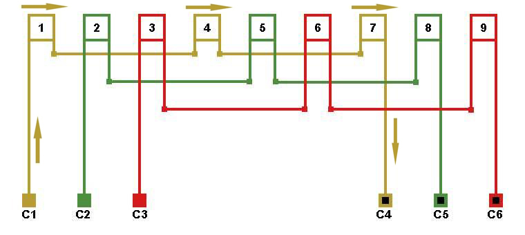
- . The figure shows that all the coils of the first phase are connected in series: the end of the first is connected to the beginning of the fourth, and the end of the fourth is connected to the beginning of the seventh. Remember the rules for drawing up a diagram of the connections of the coils in the winding of an electric motor. The direction of the current is shown by arrows from terminal C 1 to terminal C 4.
Rice. 2 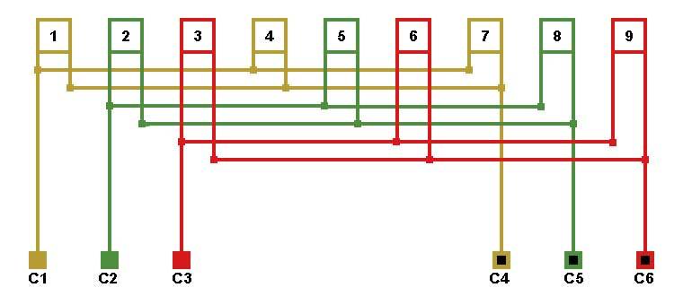
- When drawing up a connection diagram in three parallel branches, the direction of the current should not change (Fig. No. 3. The direction of the current remains from terminal C 1 to terminal C 4.
Rice. 3 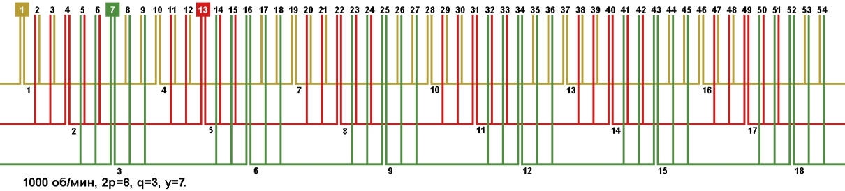
- You can also expand the possibilities for calculations if you switch from a single-layer winding to a two-layer winding (Fig. No. 4. Possible number of parallel branches: a=1, a=2, a=3, a=6, respectively, the possibility of selecting the desired wire increases.
Rice. 4
- The third calculation method can only be used for three-phase electric motors and the wrapper must know what voltage will be supplied to the motor output. Winding data of our electric motor: voltage 380 volts, winding connection in a star. We can convert the winding to a triangle phase connection, while leaving the motor supply voltage at 380 volts. When converting the winding from star to triangle, the wire cross-section is reduced by 1.73 times, and the number of turns is increased by 1.73 times. When converting the winding from a triangle to a star, the wire cross-section is increased by 1.73 times, and the number of turns is reduced by 1.73 times.
Since we are converting the engine from a star to a triangle, we reduce the wire cross-section by 1.73 times S=1.698/1.73=0.981 in the table of round wire cross-sections we find a wire with a cross-section S=0.981, a wire with a diameter of 1.12 mm is suitable. The number of turns needs to be increased by 1.73 times, 20 × 1.73 = 35 turns in the groove. After the calculation, we got a winding with new data: 35 turns in the groove, wire diameter 1.12, phase connection in a triangle.
- Fourth method of recalculation.
The fourth method of calculation is a combination of all the above methods. You can convert the electric motor given for example into three parallel branches, the connection of the phases into a triangle, and also into two or more wires. When converting the motor winding into several parallel conductors or into several parallel branches, choose thinner slot insulation.
- Parallel branches with fractional "q".
When converted into several parallel branches of an electric motor with a fractional "q", the possible number of parallel branches is equal to the number of periods in the phase. 
- As an example, let’s take a diagram for laying the winding of an electric motor with the number of slots 33, 2p=4 1500 rpm. min. rice. No. 5. Rice. 5 The order of alternation of coil groups in a period for a given engine is 2-3-3-3, one two-section coil and three three-section coils. The total number of coils in a period is 4. The figure shows that there are four coils in each phase, therefore
maximum amount
parallel branches for a given electric motor a=1. Parallel sections in coils. Before Use this type windings, read on page 310 "Windings
- electric machines
"Gervais G.K 1989 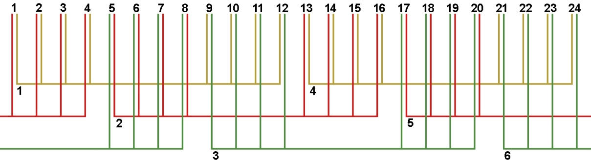
- From Figure 6 you can see that there are 4 sections in the coil, the possible number of parallel sections is a=1c, a=2c and a=4c.
Rice. 7. Laying diagram with parallel sections in the coil. 
- Since the sections in the coil are connected end to beginning, we will also connect parallel sections taking this into account.
Rice. 8. Winding connection diagram, number of parallel branches/sections a=2/2c.
Rice. 10. Winding connection diagram, number of parallel branches/sections a=2/4c.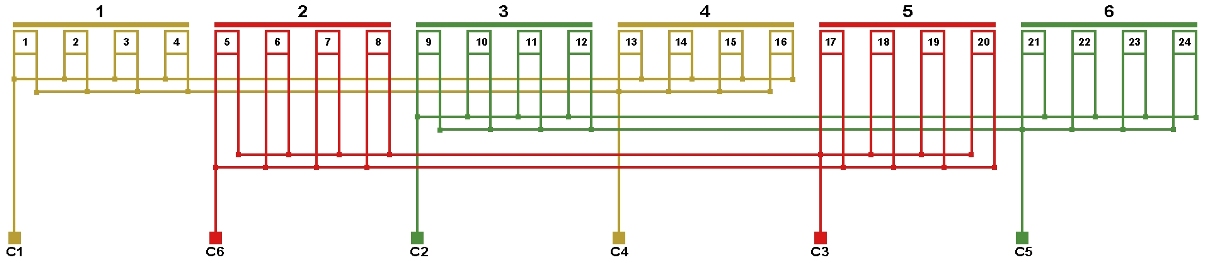
- As the number of parallel sections in the coil increases, the number of conductors in the section increases, and the cross-section of the wire decreases by the number of times the parallel sections.
Parallel windings in an electric motor.
- The calculation can be continued by dividing the electric motor winding into two, each with a power half the factory value, and connecting them in parallel. For example, let's take a 36 slot 1500 rpm motor.
Rice. 11. Laying diagram. 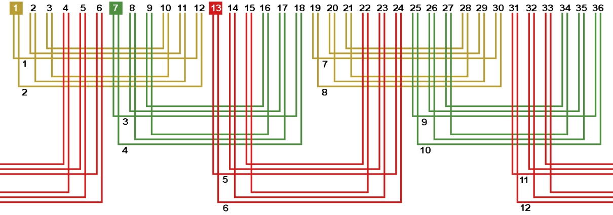
Rice. 12. Connection diagram. Number of parallel branches a=4.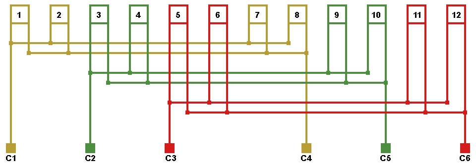
Literature on this topic:
Gervais G.K. "Windings of electrical machines" 1989
4-7. EXAMPLE OF CALCULATION OF A DC ELECTRIC MOTOR
Rated data of the electric motor: P=5 W, U=12 V, n=4,000 rpm.
According to the curve of Fig. 4-2 we determine the efficiency of the electric motor to be 30%. Using (4-2), we determine the estimated power of the electric motor:
To find the values of A and B from the curves in Fig. 4-3 we calculate the ratio of electric motor power to rotation speed, expressed in thousands of revolutions per minute. For a given electric motor, this ratio is 5:4 = 1.25. Putting this number on the horizontal axis of Fig. 4-3, we find the value of the linear load A = 5000 A/m. Similarly, we find the value of induction in the air gap B = 0.22 T. Let us take the ratio e = l/D = 1. Substituting the numerical values of the calculated quantities in (4-6), we find the diameter of the armature:
When e=1 armature length
Armature current strength according to formula (4-3)
![]()
Electromotive force of the armature winding according to the formula (4-4)
Armature pole division
![]()
Magnetic flux according to formula (4-7)
Number of armature winding conductors according to (4-8)
![]()
Number of armature slots Z = 3 2.6 = 7.8; round to the nearest odd number, Z= 7.
Number of conductors in the groove N z =620/7=88.8; round to the nearest even number, N z =88:
Cross section of the armature winding conductor at?==8 A/mm 2
![]()
The number of stator slots for electric motors with a switchable starting winding is chosen as a multiple of six. For electric motors with a power of up to 10 W, you can take 12 stator slots. Of these, 8 slots will be occupied by the working winding, and 4 by the starting winding. For electric motors of higher power, 18 slots are used. Of these, 12 slots are occupied by the working winding and 6 slots by the starting winding.
Number of turns of the working winding
Number of conductors in the groove of the working winding:
where Z p is the number of slots occupied by the working winding.
Current, A, in the working winding
Wire cross-section, mm 2, working winding
We take the wire diameter and insulation thickness according to the table. 4-1 and 4-2. The dimensions of the grooves are determined similarly to the calculation of the grooves of DC electric motors.
The starting winding occupies 1/3 of the stator slots. The number of turns of the starting winding depends on which element is switched on in series with the starting winding when starting. If active resistance serves as a starting element, then the number of turns of the starting winding is 3-4 times less than the number of turns of the working winding. But it takes up 2 times less slots. Consequently, in each slot there will be 1.5-2 times fewer conductors than in the slot of the working winding. The diameter of the wire for the starting winding can be taken smaller than for the working winding, since the starting winding is turned on for a short period of time. If a capacitor is used as a starting element, then the number of turns of the starting winding is taken equal to the number of turns of the working winding. And since it occupies 2 times less slots, then in each slot of the starting winding there will be 2 times more conductors than in the slot of the working winding. Therefore, the cross-section of the starting winding wire must be taken 2 times smaller. The winding circuit is drawn up according to § 3-6.
The number of rotor slots is selected depending on the number of stator slots. With 12 stator slots, you can take 9 rotor slots, with 18 stator slots, 15 rotor slots. The diameter of the rotor slot is selected so that the total cross-section of the rotor rods is 1.5-2 times larger than the total cross-section of the conductors of the working stator winding. Copper rods are hammered into the rotor grooves, which are soldered to the closing rings at the ends of the rotor. The cross-section of the closing ring should be approximately three times larger than the cross-section of the rod.
The starting torque of the electric motor depends on the resistance of the rotor winding. Therefore, for electric motors with high starting torque, the rotor rods should be made of brass or bronze.
The air gap between the stator and the rotor in asynchronous electric motors should be kept as small as possible so that the rotor does not touch the stator. The larger the gap, the more current is required to create magnetic flux. In factory-made electric motors, the gap is 0.25 mm per side. IN homemade electric motors With such a small gap, the rotor may touch the stator. Therefore, the gap has to be taken 0.3 or even 0.4 mm.
It is recommended to select the active resistance or capacitance of the capacitor used as starting elements experimentally when testing the manufactured electric motor. According to the experience of manufactured electric motors, the active starting resistance is approximately twice the resistance of the starting winding.
The resistance of the starting winding can be determined as follows. The average length of a turn of the starting winding is approximately four times the length of the stator. The unfolded length of the winding can be found by multiplying the length of the middle turn by the number of turns. The winding resistance can be determined from the table. 4-1, which indicates the resistance of 100 m of wire.
The capacity of the starting capacitor for an electric motor at a voltage of 120 V should be about 3-10 µF. It should be borne in mind that a voltage is generated at the terminals of the capacitor that significantly exceeds the voltage of the lighting network. Therefore, when starting a capacitor electric motor, precautions must be taken. The capacitor terminals must not be left open. Capacitors must be selected for triple the voltage of the electric motor in order to avoid their breakdown. It is advisable to use capacitors only for electric motors operating from the lighting network. As the voltage decreases, the required capacitance of the capacitor increases quadratically. Therefore, for electric motors with a voltage of 12 V, it would be necessary to take capacitors of huge capacity.
4-13. EXAMPLE OF CALCULATION OF A SINGLE-PHASE INDUCTION ELECTRIC MOTOR WITH A STARTING WINDING
Rated data: power 3 W, voltage 120 V, rotation speed (synchronous) 3,000 rpm, intermittent operation of the electric motor with an on-time of 25%,
According to the curve of Fig. 4-9 product ηcosφ=0.08.
The estimated power of the electric motor is determined by (4-33):
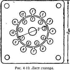
The outer diameter of the stator is determined by (4-34):
To simplify manufacturing, let's take the shape of the stator in the form of a square (Fig. 4-10).
The inner diameter of the stator is determined by (4-35);
Stator length
Pole division
The number of rotor slots is taken to be 9.
The total cross-section of copper in the grooves of the working stator winding
Total cross section of copper in the rotor slots
Rotor rod section
Rotor Rod Diameter
Rotor groove diameter with allowance for driving rods
Diameter of the circle on which the centers of the rotor slots are located:
Distance between adjacent grooves
![]()
Tooth thickness at narrow point
The bevel of the groove is per one groove division of the stator, i.e. 30°.
4-14. CALCULATION OF CAPACITOR ELECTRIC MOTOR
The calculation of a capacitor electric motor has some features compared to the calculation of an electric motor with starting windings. In a capacitor motor, both windings remain on all the time.
When determining the design power, the product ηcosφ for a capacitor electric motor is taken equal to 0.5. To obtain a symmetrical winding, the number of stator slots is taken as a multiple of eight. Half of the slots are occupied by the working winding, and the other half by the auxiliary winding. In Fig. Figure 3-13 shows a diagram of the stator winding of a capacitor motor. Solid lines show the coils of the working winding, and dotted lines show the coils of the auxiliary winding. Both windings can be made exactly the same, that is, from the same wire with the same number of turns.
The current in each winding is determined by the formula
Otherwise, the calculation of a capacitor electric motor is similar to the calculation of an electric motor with starting windings.
The capacitor electric motor can be made with either a short-circuited rotor winding or a massive rotor. A second capacitor is usually used as a starting element. The capacity of the starting capacitor is approximately 3 times greater than the capacity of the working capacitor in the auxiliary winding circuit.
N.V. Vinogradov, Yu.N. Vinogradov
How to calculate and make an electric motor yourself
Moscow 1974