The purpose of internal combustion engine supercharging systems is to increase the mass filling of the engine cylinders with fresh charge. This is usually achieved with the help of special devices or supercharging units. Engines with such systems are called combined. Supercharging systems are very diverse in their operating principles and, accordingly, in their classification criteria.
In combined internal combustion engines, the air or combustible mixture is compressed in compressors before entering the cylinders. Boost is considered low if the compressor has k< 1.9. Низкий наддув позволяет повысить мощность двигателей на 20-25%. При среднем наддуве ( к = 1.9-2.5) удается повысить ее на 25-50%. Высокий наддув ( к >2.5) further increases the power, but its use is often not justified due to a significant increase in the mechanical and thermal stress of parts and assemblies.
The supercharging of engine cylinders can be either dynamic or carried out using a special supercharger (compressor). In modern internal combustion engines, both volumetric (rotary-gear, screw, piston) and bladed centrifugal compressors are used for pressurization. Gas turbines are most often radial-axial, less often - axial.
There are three supercharging systems using superchargers: with a drive compressor, with a turbocharger and combined (Fig. 11.1).
Fig. 11.1. Diagrams of internal combustion engine supercharging systems
In the first scheme, the drive compressor is connected to the engine crankshaft through an overdrive gear. To drive the turbocharger (Scheme 2), the energy of the exhaust gases entering the gas turbine is used . The compressor is installed on the same shaft as the gas turbine . In the case of a combined system (scheme 3), the first stage is the drive compressor, and the second is the turbocharger. Two-stage charging can be carried out by two turbochargers or drive compressors arranged in series.
Gas turbine supercharging is most often used on tractor and automobile diesel engines.
In this case, there are two main options for using energy:
1. The energy consumed by the compressor is equal to the energy produced by the gas turbine. In this case, the turbocharger has only a gas connection with the engine (Fig. 11.1.2). This scheme provides high economic performance with maximum design simplification and is therefore the most common. In such engines, the energy of exhaust gases is utilized, which in some cases even makes it possible to increase the efficiency of the engine.
2. The energy produced by a gas turbine is not equal to the energy consumed by the compressor. The difference in energy is transferred from the engine to the turbocharger through the use of a mechanical connection between the turbocharger rotor and the engine crankshaft, which complicates the design of the latter. Sometimes in these cases, instead of a mechanical connection between the turbocharger rotor and the crankshaft, a combined charging system is used.
Mechanical coupling is also used in cases where it is necessary to transfer excess energy from a gas turbine to the engine at high boost pressures and gas temperatures in front of the turbine.
Possible two options gas supply to the gas turbine:
1) from a common outlet pipeline;
2) separately from each cylinder or from a group of cylinders, in which, in accordance with the order of their operation, the time between two successive pressure pulses formed when gases are released from the cylinders turns out to be sufficiently large (pulse boost).
In the first case, especially in engines with a large number of cylinders and a high rotation speed, the gas pressure in the exhaust pipe is equalized, the amplitude of pressure fluctuations in front of the turbine is small, and the process of supplying gases to the turbine can be considered as occurring at constant pressure. In the second case, the exhaust gases enter the gas turbine with variable pressure, which allows, under certain conditions, to increase the efficiency of charging.
The supply of gases to the turbine at constant pressure creates increased resistance in the engine exhaust tract compared to release into the atmosphere. This impairs cleaning of the cylinders and reduces their filling with fresh charge.
With pulse boost, after a period of gases being released from one cylinder, the pressure in the exhaust tract decreases sharply until the valves begin to overlap. As a result, the pressure difference between the intake and exhaust tracts increases and cleaning of the combustion chambers becomes more efficient. The work required to expel gases is reduced. As the boost pressure increases and the average gas pressure in the exhaust tract increases, the positive effect of using pulse boost decreases, since the pressure pulses are smoothed out. The maximum effect in a pulse boost system is achieved at p to < 0.15 MPa, at p to< 0.4 МПа применение импульсного наддува уже не дает эффекта. Для достижения наибольшего эффекта при импульсном наддуве выпускные трубопроводы делают по возможности короткими и меньшего объема. В импульсных системах используется кинетическая энергия отработавших газов, однако, ухудшается очистка цилиндров двигателя от отработавших газов, что является общим недостатком всех систем газотурбинного наддува.
In automotive diesel engines with 8 or more cylinders, systems with constant pressure in front of the turbine are predominantly used. The efficiency of such turbines is higher than that of pulse turbines, and the exhaust system is simpler.
It should also be noted that supercharged engines have less adaptability (compared to naturally aspirated engines) and worse starting properties.
Air coolers
During supercharging, the air temperature behind the compressor increases, therefore, at medium and high supercharging, intermediate cooling of the air is carried out between the compressor and the engine intake pipe. This helps to improve the mass filling of the cylinders, increase the power and fuel efficiency of the engine, reduce the thermal stress of its parts, and reduce the temperature of the gases in front of the turbine.
The air can be cooled with special coolers or through evaporative cooling - injection of easily evaporating substances (alcohol, ammonia, water, etc.) into the air. Two types of coolers are used: air-to-air and water-to-air. Both tubular and plate coolers are used.
The air-to-air cooler is installed in front of the engine oil and water radiators. Atmospheric air is sucked through the cooler by a fan of the engine cooling system. The cooled air moves inside the brass tubes of the cooler core, similar to those usually used in radiators of the cooling system.
With water-air cooling, water circulates through the cooler and radiator using a pump (special or available in the engine cooling system).
Although the heat exchange between the cooled air and the coolant, all other things being equal, occurs more intensely than between the cooled and the cooling air, in general, air-to-air coolers are more efficient than water-to-air coolers due to the greater temperature difference between the air and the coolant.
Supercharging - “Artificial respiration” for the engine
The “iron” 20th century is coming to an end. Our favorite car witnessed and took part in the events of this century, improved and transformed along with man’s ideas about a mass-produced vehicle. And on the eve of the magical number 2000, it makes sense to talk about the most important technical principles and solutions used in the design of a car, remember their history and look into the future. The use of supercharging to supply air to internal combustion engines is one such topic. In addition to the historical aspect, talking about supercharging also has a purely practical meaning - after all, there are more and more cars equipped with such devices on our roads.

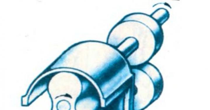
 Design and principle of operation of a rotary-gear compressor of the Roots type
SUPERCHARGING AS A CURE FOR SHARP
How a piston internal combustion engine works was known back in the last century. The mixture of air and fuel, after being compressed in the cylinder, ignites, expands during combustion, pushing the piston and performing useful work, and then flies out into the exhaust pipe in the form of exhaust gases.
As soon as rattling horseless carriages with piston engines appeared on the roads of the world, the struggle of designers began to increase engine power. The extensive method - burning more fuel in the cylinders, increasing the displacement - led to the appearance of ten- and twelve-liter multi-cylinder monsters. And thoughts about that. How to intensify work processes and remove more horsepower from the engine led motorists to the idea of supercharging.
The fact is that the amount of fuel that can burn in the engine cylinders is strictly related to the volume of air sucked in by the engine during intake. The mass ratio - approximately 1 kg of fuel to 15 kg of air - had to be maintained very strictly, since an over-enriched mixture led, on the contrary, to a drop in power.
How to overcome this limitation? The idea is obvious: supply more air to the cylinders, pumping its iodine with excess pressure!
First, drive, or, in other words, mechanical superchargers appeared - rotary, screw, piston, spiral types, driven into rotation by a mechanical transmission from the engine crankshaft. Gottlieb Daimler experimented with similar devices - his first experiments with supercharging date back to 1885 - and, a little later, Rudolf Diesel. But it turned out to be a tough nut to crack - and when implementing a rather simple idea, the designers had to face a lot of technical difficulties.
As often happens, the military was the first to use mechanical supercharging - on aircraft engines to compensate for the deterioration of cylinder filling during high-altitude flights. It was only after the First World War that the experience gained made it possible to equip gasoline engines with drive superchargers, first in racing cars, and then in sports and touring cars. Overseas in the 1920s, compressors were produced by Duesenberg. Auburn and Cord, and among the “Europeans” Bentley was in the lead. Lancia, Alfa Romeo, Fiat, Bugaiti and, of course, Daimler-Benz - sports “compressor” SS and SSK with switchable Roots-type rotary supercharger drive have become the dream of any collector. The seven-liter six-cylinder engine of the SSKL racing roadster of the late 20s with mechanical supercharging developed 300 hp. e.! By the way, these cars were designed by Ferdinand Porsche himself, who was technical director in Stuttgart at that time.
The idea of supercharging turned out to be very fruitful. We increase the air pressure by 30% - we get an adequate increase in engine power. We add up to 50% - we remove even more “horses”. And so on until... the engine falls apart - after all, compression now begins not at atmospheric pressure inside the cylinders, but at excess pressure, and the actual compression when the supercharger is running will be higher. At the same time, not only power increases, but also the thermal and mechanical load on engine parts. And, of course, the increase in boost pressure of gasoline engines is restrained by the detonation resistance of the fuel - if the compression is too high, then the combustion process of the mixture will take on the character of an explosion, with all the ensuing detonation “charms”...

The Roots compressor was mounted in front of the 7-liter “six”, and its housing and manifold were equipped with fins for better cooling

The most common gas exchange scheme these days is with turbocharging and wastegate
Mechanical superchargers have two main advantages. Firstly, it is an almost inertia-free reaction to changes in fuel supply and, secondly, a wide range of engine speeds at which such boost is effective. Modern drive compressors are famous for the fact that they work from the very bottom, almost from idle speed, increasing torque where its lack is felt most strongly.
But there are also disadvantages. The comparative “high speed” of drive superchargers (up to 20,000 rpm or more) gives rise to technological difficulties in manufacturing, and the rather large dimensions lead to layout problems: there is nowhere for an apple to fall inside modern engine compartments...
And the main disadvantage of such a scheme is that the energy for the operation of the supercharger is taken from the crankshaft, taking away a small but still noticeable, about 10%, share of the torque. Of course, this is compensated by an increase in boost pressure, but still...
ENERGY FROM NOWHERE
Drive compressors of those years were very complex and unreliable. For example, the supercharger of the legendary MercedesBenz SSK.L had to be connected only at high speeds (about 4000 rpm) and high speeds and only for 20 seconds - in order to break away from the opponent or complete overtaking. At the same time, the compressor emitted a heartbreaking screech: its rotors rotated four times faster than the crankshaft, quickly reducing the engine's life and its own. It was not for nothing that Sir Bentley, whose cars were then the main rivals of Porsche’s creations in racing, did not like superchargers, but against his will they were installed on 4.5-liter engines at the request of racers.
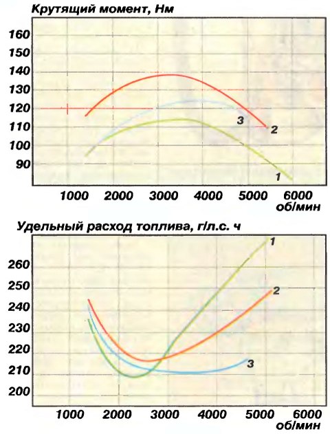
This is the nature of the change in torque and specific fuel consumption of the VAZ-2106 engine with a NAMI turbocharger (1 - standard engine, 2 -power option for tuning the turbocharger, 3 - economical option)
Gas turbine or simply turbocharging does not have this drawback. It is powered by engine exhaust gases, which usually simply fly out into the chimney, carrying with them and dissipating in the atmosphere a little less than half of the total fuel combustion energy.
Unlike drive superchargers, the designs of which vary greatly depending on the type, all turbochargers operate on the same principle and have a similar design. Instead of a receiving pipe, a turbine housing is attached to the output flange of the engine exhaust manifold - a cast “snail”, inside of which a turbine wheel rotates under the influence of the exhaust gas flow. The torque is transmitted to the coaxial compressor wheel, which rotates in its “snail”, sucking in the air entering through the filter and supplying it under pressure to the carburetor or to the intake manifold. This improves cylinder filling and increases engine power.
As simple as it is ingenious, the idea of turbocharging turned out to be extremely difficult to implement. The temperature of the exhaust gases that the turbine must withstand is 900-950 °C, and the operating speed of the turbocharger is tens and even hundreds of thousands of revolutions per minute! Gas turbine supercharging was studied at the beginning of the century - the Swiss engineer Alfred Büchi carried out his first experiments before the First World War. Like drive compressors, turbocharging first appeared on aircraft engines. For example, the Frenchman Professor Rato in 1919 equipped the engine of a Breguet airplane with a turbocharger and an intercooler (!) - and the “supercharged” airplane immediately broke the altitude record, breaking through the ten-kilometer mark
But the main obstacle to the widespread use of turbocharging until the 60s remained the lack of inexpensive technology for high-precision casting from heat-resistant materials.
The first production car with a gasoline engine equipped with a turbocharger was the infamous rear-engine Chevrolet Corvair - the one that is “dangerous at any speed.” An air-cooled opposed six, which in its naturally aspirated version produced 95 hp from its 2300 cc. That is, in the turbo version on the 1961 Corvair Monza spider it developed 140, and later 180 hp. e.!
But oversteer, which was initially characteristic of this extraordinary “American,” ruined the Corvair - after lawyer Ralph Neider’s acclaimed book “Unsafe at any speed,” demand for the car fell sharply, and even subsequent modernizations could not rehabilitate the Corvair in the eyes of conservative Yankees. A shadow of disrepute has also fallen on the innocent turbocharger...

Turbocharger rotor: at the top - brand new, at the bottom - ruined by poor-quality lubrication

Thrust and axial bearings made of lead bronze, the life of which came to an untimely end due to the carelessness of the owners...

Torque curves of three Volkswagen engines: naturally aspirated 1.8-liter, 1.5-liter 16-valve and 1.3-liter turbocharged (turbo) and mechanical supercharger (kompr.)

Differences in response latency to feed increasesfuel (engine speed - 2300 rpm, 4th gear). The turbocharger “thinks” a second longer than the drive supercharger!
The next appearance of a turbocharger on passenger cars occurred only a decade later in Mother Europe - 1,600 high-spirited BMW 2002 turbos produced by the company from 1973 to 1974 did not make much of a difference, but showed the way to others. The era of mass-produced turbo engines was ushered in by Porsche cars (911 turbo, 1974) and SAAB 99 turbo, 1978). Well, after 980 goals, technological barriers collapsed, and turbo versions appeared in the model range of almost all leading manufacturers.
Turbocharging was established on diesel engines earlier, but not on passenger cars, but on heavy vehicles - ships, tanks, trucks... The fact is that adapting a turbo unit to a diesel engine is easier than to a gasoline engine: in diesel engines, the energy of the exhaust gases at low speeds is greater . And it’s easier for the turbine to work - the temperature of the diesel exhaust gases does not rise above 650-700 "C. The initiator of the mass use of turbodiesels on civilian trucks was DAF in 1958. And on passenger cars, turbodiesels began to appear only in the early 80s, when between the leading Automakers were already in full swing, fiercely fueled by fuel crises and protests by “greens,” to reduce fuel consumption and air pollution.
WHAT IS HIDDEN IN “SNAILS”
As mentioned, although the idea is simple, a turbocharger is very complex to design and manufacture. And especially for a passenger car.
Because compactness requirements increase the cost of the casting process. That is why only specialized companies undertake the production of turbochargers - Garrett (USA), KK (Germany), Holset (England), IHI (Japan) - and it is cheaper for automobile companies to buy units from them. The exceptions are Mitsubishi and Nissan, which have mastered the production of turbochargers on their own and even sell them “outside” (for example, Mitsubishi equipped its SAAB engines with units).
The turbocharger housing and turbine “scroll” are cast from special malleable cast iron, which has high heat resistance, but, alas, can crack if there is a sharp temperature change - for example, when water gets in. Inside the housing, in sliding bearings made of lead bronze, an axis rotates, on one side of which there is a welded turbine wheel made of a heat-resistant alloy, and the compressor impeller is attached to the other end - it, like its “snail”, is not so loaded with heat, which makes it possible to cast these parts made of aluminum alloys.
The shaft is kept from axial movements by a thrust bearing made in the form of a wide washer with a slot. All bearings are lubricated with engine oil, which comes under pressure from the engine lubrication system - supply and drain oil lines are connected to the turbocharger housing. There are also water-cooled units, but rarely
The shaft with impellers is carefully balanced after assembly - the slightest imbalance will cause vibration of the rotor and will inevitably damage the turbocharger. After all, the operating speed of the shaft can exceed 200,000 rpm!
At first, turbochargers were characterized by very large delays in “response”: you have already pressed the gas pedal, but the engine is still waiting and waiting... This is the so-called turbo lag - turbolag. And also - they refused to work at low and medium speeds, when the exhaust gas pressure is low (“turbojam” - a failure of the engine’s torque characteristics up to 2500-3500 rpm). For example, the turbocharger on a Chevrolet Corvair began to work only after the boxer engine spun up to 5000 rpm - almost to maximum speed. This was dealt with by reducing the mass and moment of inertia of the rotor. At the same time, the boost pressure increased in the low-speed zone, but as they increased, excess was formed, which must be “bleeded off” so that the engine does not experience a “hypertensive crisis.”

Curves illustrating the “thermal shock” of turbocharger bearings when the engine stops. Exhaust gas temperature -950 °C
Therefore, all turbochargers of gasoline, and later diesel, engines began to be equipped with a boost pressure regulator. As a rule, it operates at a certain threshold value of the charge air pressure in the compressor - the air presses on the membrane, overcoming the resistance of a calibrated spring, and, through mechanical traction, slightly opens the bypass valve in the turbine housing, diverting part of the exhaust gases past the turbine wheel. Previously, other control schemes were encountered - for example, based on the pressure of the exhaust gases themselves. And now on modern engines this is controlled by electronics.
Of course, when bypassing, the efficiency of the turbocharger decreases, but so far few have been able to avoid this by regulating the performance of the turbocharger in another way - for example, by changing the angle of influence of the exhaust gas flow on the turbine blades depending on the rotor speed. Turbocompressors with variable nozzle geometry, in which the angle of inclination of the nozzle blades is adjusted by a pneumomechanical drive, are produced only by Garrett and a few other leading companies.
DISEASES AND CARE
The turbocharging unit is designed as maintenance-free, that is, it does not require any specific maintenance or adjustment, and after the service life has expired, which is usually equal to or exceeds the service life of the engine itself, it must be replaced. However, it is possible to formulate a few simple recommendations that will arm the owner of a car with a turbo engine with knowledge of situations in which it is undesirable to get into.
Rotor bearings are the main component of a turbocharger, on which the performance of the entire unit mainly depends. And they mainly need abundant and high-quality lubrication. Therefore, the simplest advice - regularly, according to the instructions, change the filter and oil in the engine and monitor its level - should become an iron commandment for the owner of a turbo engine. The oil can be either synthetic or mineral based - this is not so significant. In general, when choosing the type of lubricant, it is better to follow the factory instructions and under no circumstances mix oils, even of the same type, but of different grades. The main thing is that the API oil quality class must be at least SG/CD. It is this index that indicates the quality of the additive package, which must be designed to work in the most intense zone of the turbocharger bearing assembly, where both friction conditions and oil temperature can reach extreme values.
But the oil not only lubricates the bearings, but also cools the assembly, maintaining the temperature at an acceptable level. If lubrication conditions worsen - for example, the oil has not been changed for a long time, and deposits have reduced the throughput of the lines - then the oil begins to stagnate in the bearing assembly, which increases the thermal stress, and this causes coking and even greater clogging of the line. As a result, the bearings sooner or later remain dry, and this is followed by their scuffing and breakdown of the entire unit.
Another turbocharger unit, the serviceability of which also affects the “health” of the engine, is the gas-oil seals of the rotor axis, usually made in the form of elastic steel rings such as piston ones. They isolate the lubrication system from the intake and exhaust cavities of the turbocharger, and when they wear out - and this usually follows radial runout of the rotor or play of its axis - the oil begins to be squeezed into the compressor cavity, enters the cylinders and burns with a characteristic bluish smoke. The owner is sinning on the “piston”, but the problem is in the turbocharger!
At first, this effect manifests itself when starting a cooled engine - a puff of blue smoke from the exhaust pipe may indicate the beginning of wear of the bearing unit and seals. But wear, for example, of oil seals or valve guides of the engine itself also manifests itself in exactly the same way...
By the way, a similar picture can be caused by... a clogged air filter! When it exerts significant intake resistance, an increased vacuum occurs in the manifold, especially at idle speed in gasoline engines, for which the seals are simply not designed.
Affects the performance of the turbocharger and the condition of the engine itself. For example, when piston rings wear out, the resulting excess pressure of crankcase gases can prevent the oil from draining from the turbo unit - with corresponding consequences. The same effect is observed when crankcase ventilation deteriorates. And a violation of the fuel adjustments - a malfunction of the injection system - can lead to the fact that carbon deposits formed during incomplete combustion of fuel will be deposited on the turbine wheel and bypass valve, causing an imbalance of the rotor and interfering with the normal operation of the pressure regulator.
The serviceability of the turbocharger can be judged both by the dynamics of acceleration and by the charge air pressure. As a rule, all cars with gasoline turbo engines are equipped with dial gauges for boost pressure in the instrument cluster. At idle, the instrument needle shows a vacuum in the intake manifold and reacts to “gas leaks” without load with a weak deviation. But when accelerating, say, in third gear from low speeds, you can clearly see how after opening the throttle flow damper "to the floor" yes The boost pressure (and acceleration of the car) increases slowly at first, and then - in the region of 2000-2500 rpm on modern cars - the arrow sharply goes to the right all the way, a muffled whistling sound of a turbine is heard from under the hood, and the car powerfully rushes forward. Some people like this “turbo buzz”, others find it difficult to predict the car’s reaction to changes in fuel supply - it’s a matter of taste. In the end, some companies (Opel, Citroen, SAAB) offer the most “charged” versions either with “explosive” four-cylinder turbo engines, or with “smooth” and more torquey “sixes” at low speeds...
And finally, some driving recommendations. There are no special requirements for warming up turbo engines - a working lubrication system with a normal filter ensures an instant supply of oil to the supercharger bearings. But when you turn off the engine after hard driving, when the engine has been running for a long time under heavy load high speeds, it is better to let it idle for a minute or two. The fact is that stopping oil circulation after intense work causes “thermal shock” - cooling abruptly stops, and the oil in the bearing housing of the turbo unit heats up to three hundred degrees, coking and forming deposits. And in extreme cases - for example, when stopping after a long slip in the mud, when the turbine “snail” is red-hot, the rotor bearings can jam and even melt...

Garrett VNT25 turbocharger with variable nozzle geometry. Since 1991 it has been installed on the Fiat Croma 2.5 TD diesel car.

In the NAMI turbocharging laboratory, the adaptation of the turbocharger to the “eight” engine is in full swing. The results are just around the corner...
And before overcoming water obstacles, you need to assess the depth of the ford - the cast-iron turbine housing may crack after “water procedures,” especially on gasoline engines, where it is more heated.
PROS AND CONS OF TURBOCHARGING
Let's start with the cons. A turbocharged engine (and supercharged engine in general) is more complex and expensive both to manufacture and to operate - it requires the best oil, and the lubricant needs to be changed more often. It is still not possible to avoid “turbo lag” and delays inherent in gas turbine supercharging. These phenomena can be reduced by the use of two turbochargers connected in series, “tuned” in different ways - this scheme is called biturbo and was widely used in motorsports, and in passenger cars it was first installed on the car of the same name by Maserati. But, alas, a “biturbo” engine is even more expensive.
And, of course, the engine itself experiences heavy loads, and the increase in thermal stress and mechanical loads is proportional to the increase in boost pressure (and therefore power). Therefore, on serial turbo engines the pressure is limited to 0.3-0.8 kg/sq.cm, making do with a very modest boost by 30-50% by sporting standards. But this allows, by strengthening the engine parts (piston, connecting rod, etc.), to maintain the engine resource at the “atmospheric” level.
The intercooler, which is an aluminum radiator-heat exchanger included in the intake tract between the compressor and the manifold, allows you to painlessly increase the pressure by another 10-20 percent. It quite effectively reduces the temperature of the compressed air and the heat flow through the engine, allowing more fuel to be burned in the cylinders without the risk of detonation. But again, not cheap...
Well, the advantages of turbocharging - increased liter power, engine efficiency, improved acceleration dynamics, elasticity and (compared to an “aspirated” engine of the same power) fuel efficiency - are obvious. In addition, the use of supercharging makes it possible to reduce the amount of toxic emissions - CO and CH, and with intermediate cooling of the air, also nitrogen oxides NOx. And recently, new arguments in favor of supercharging have appeared.
XXI CENTURY - WITH OR WITHOUT SUPERCHARGE?
Since the second half of the 80s, the world's leading automobile manufacturers have been investing millions of dollars in research and development to reduce toxicity and reduce fuel consumption, while simultaneously striving to increase liter power. Gradually introducing solutions such as replacing the carburetor with injection, electronic optimization of operating modes, catalytic neutralization, resonant intake and exhaust, adjustable phases, engineers brought the Otto four-stroke engine to almost perfection. All that remains is to use direct injection on gasoline engines, which is what Mitsubishi and Subaru are now doing among the first. What's next?
It seems that at the beginning of the next century the internal combustion engine will still prevail over other alternative power plants. And in order to meet very stringent toxicity standards, known as Euro 3, designers will have to look for new ways to radically modernize piston engines. And most likely, you won’t be able to forget about supercharging.
One of the ways is to create engines that implement cycles with internal cooling (Miller-Atkinson cycles) with the mandatory use of supercharging, either mechanical or combined.
The second way is to switch to... a two-stroke cycle! Theoretically, it can provide better performance, and therefore the heirs of the funny DKW engines are now spinning on the test benches of Ford and Jaguar. Again, armed with supercharging...
The third direction is the use, along with direct injection, of various supercharging schemes to ensure the operation of gasoline engines on ultra-lean mixtures. Some offer a combination of a switchable drive supercharger for low speeds and turbocharging for mid and high speeds. Well, some continue to work on another type of supercharging unit - a wave pressure exchanger
Sotrgekh, combining the advantages of all traditional types of superchargers, but extremely difficult to develop and manufacture.
Improvements are also being made to good old turbocharging. Thanks to the use of ceramics and special plastics, the mass and moment of inertia of the rotor are reduced, gas-lubricated bearings and new seals will reduce friction losses...
So we are on the verge of new significant changes in engine design - and Autoreview, of course. will pay attention to any interesting innovations. It is a pity that Russia is a hopeless outsider in this race.
Although our domestic developments, perhaps, could compete with the “offal” of concept cars from famous companies. It’s nice that the NAMI turbocharging laboratory continues its scientific research and practical development with sheer enthusiasm. For example, a turbocharging unit for “classic” VAZ engines has been made and tested, and a turbocharger for “eighth” engines is being prepared. We will tell you more about them later. By the way, they will try to help those poor souls who suffer from faulty turbocharging of foreign cars...
A. AZBEL L. GOLOVANOV
In order to burn more fuel in the volume of the cylinder and, as a result, obtain greater useful power, it is necessary to proportionally increase the amount of air from the condition α ≈ const. This problem found its solution in supercharging. Supercharging is an increase in the charge of air supplied to the cylinder due to an increase in its density as a result of pre-compression to a pressure P k > P o , and accordingly an increase in the amount of fuel burned. The degree of boosting of diesel engines by supercharging is estimated by the “degree of supercharging” λ n:
λ n= R en / R e, (№1)
Where R e And R en — average effective pressure of the engine without supercharging and with supercharging.
In principle, the amount of air in the cylinder can be increased not only by precompressing it, but also by lowering the temperature (the specific gravity of air is proportional to Pk and inversely proportional to Tk: γk / γo = Pk To / Po Tk), as well as by increasing the cylinder filling factor η n by better cleaning the cylinder. These factors are used in combination when supercharging. So, after preliminary compression, the air is cooled to a temperature of 30÷45 o C, after which it is supplied to the cylinder. Better cylinder cleaning is ensured by careful development of the gas exchange system and the use of combustion chamber purging in 4-stroke internal combustion engines.
Gas turbocharger of a marine diesel engine
The use of supercharging made it possible to increase the cylinder power of diesel engines by 4–5 times compared to naturally aspirated engines, but required the solution of a number of serious technical problems associated with increased mechanical and, deterioration of lubrication conditions, increased wear of the cylinder-piston group, coordination of the characteristics of supercharging and diesel units etc. These problems constantly confront diesel manufacturers with further boosting of engines.
The following methods of supercharging are distinguished:
- Inertial;
- Mechanical;
- Gas turbine and combined.
Attempts to use inertial supercharging took place in the initial period of boosting 4-stroke internal combustion engines. In this case, each cylinder was supplied with a specially selected long intake pipe. An increase in air pressure at the end of the intake was achieved due to the kinetic energy of the air column in the intake pipe and the corresponding organization of resonant oscillations in it. Inertial supercharging made it possible to increase power by 15÷25%.
 Inertial charging of a marine engine
 With mechanical charging, the air blower is driven by the engine crankshaft. Piston, rotary or centrifugal compressors are used as superchargers, driven from the crankshaft directly or through a gear ( gear, chain, electric).
The most widely used methods in internal combustion engines are gas turbine and combined charging methods. With gas turbine charging, the energy of the exhaust gases is used to drive the supercharger. A gas turbine and a centrifugal compressor sitting on the same shaft constitute a single unit - a gas turbocharger (GT). Gases from the working cylinders, giving part of the energy to the gas turbine, are sent further to the recovery boiler and into the atmosphere. Air sucked from the atmosphere is compressed in a compressor to pressure Pk, supplied to the air cooler and then to the purge receiver and working cylinders. With slight compression in the compressor, when the temperature does not rise above 45÷50 o C, the refrigerator may be absent.
Combined supercharging means a system that simultaneously uses gas turbine and mechanical supercharging. It is resorted to in cases where the power of gas turbines is insufficient to drive the supercharger. A special case of a mechanical supercharger is the use of working cylinders of crosshead engines in conjunction with a gas turbocharger.
 Mechanical supercharging of a marine diesel engine
 An assessment of the degree of perfection of a particular supercharging system can be given on the basis of a qualitative analysis of the mechanical efficiency of the engine. For a naturally aspirated engine, a relationship can be written;
ηfur= Ne/ Ni = (Ni - Nmex) / Ni = 1 - Nmex / Ni:
η fur= 1 - N fur / Ni
With inertial charging, all other things being equal, the power of mechanical losses of the engine N mech will not change, but will increase without any additional energy costs for driving the air supercharger. Consequently, the mechanical efficiency of the engine will increase. However, inertial charging has not found application in marine diesel engines due to the bulkiness of the intake system and the relatively low level of boost.
In an engine with mechanical supercharging, the power of mechanical losses increases by the amount NB of the cost of driving the air supercharger; mechanical efficiency is:
η mn fur= 1 - ((N fur + Nв) / (Ni + ΔNi)), (№2)
Where Ni + ΔNi= N in— indicated power of the supercharged engine.
Obviously, any increase in diesel power requires an increase in boost pressure Pk. At the same time, the power Nв for the air supercharger drive also increases. If the indicator power increases more rapidly than the power of mechanical losses, then the mechanical efficiency increases. In this case, as Pk increases, the average effective pressure Ren also increases: Re n = Pi n η mn fur.
When a certain boost level is reached, the cost of driving a mechanical air supercharger begins to grow more rapidly than the increase in indicated power; mechanical efficiency decreases. Despite the increase in Pk, the average effective pressure may even decrease (if the degree of decrease in η mech exceeds the degree of increase in Pi). In the limiting case of mechanical supercharging, it is possible to create an engine in which all the indicator work will be absorbed by the compressor, the mechanical and effective efficiency will be equal to zero.
According to experimental data, the limit of a reasonable increase in An with purely mechanical supercharging is within the limits:
λн= 1.2÷1.3.
Wherein RK= 1.3÷1.5 or η mn fur= 0.70÷0.85.
With further boosting of the engines, too much power is required to drive the supercharger, which reduces η mech and η e. For this reason, purely mechanical supercharging is not used in modern engines. It can be found in engines of older design ( ZD-100, 37D, DR 30/50, DR 43/61 and etc.).
One of the most effective ways to increase the cylinder power of an internal combustion engine is supercharging. In supercharged marine internal combustion engines, air enters the cylinders under a certain pressure created in special charging units installed on the engine. By increasing the mass of the air charge and cyclic fuel supply, a significant increase in cylinder power and power of the entire internal combustion engine is achieved.
Supercharging systems consist of charging units (compressors), air coolers, distribution bodies and receivers. Depending on the compressor drive, pressurization is divided into mechanical, gas turbine and combined. In internal combustion engine with mechanical supercharging A centrifugal, rotary or piston air blower is driven from the engine crankshaft, which consumes 10% or more of the effective power and reduces engine efficiency. Mechanical supercharging is used in low-power marine internal combustion engines.
Gas turbine charging diagram:
Usage gas turbine supercharging makes it possible to increase engine power within a wider range than with mechanical supercharging. In this case, air is supplied to the engine intake receiver through the air cooler IN compressor TO driven by a gas turbine T, using the energy of exhaust gases. The compressor and gas turbine are combined into one unit, which is called a gas turbine compressor (GTC). Depending on the purpose of the internal combustion engine, the turbine operates at constant or variable exhaust gas pressure, the average temperature of which in front of the turbine is 400 - 450 C. Gas turbine supercharging is widely used in four-stroke internal combustion engines, as well as in low-speed two-stroke internal combustion engines with direct-flow valve purge.
Combined boost It is mainly used in powerful low-speed two-stroke internal combustion engines with loop blowing, when the power of gas turbines is insufficient to drive the air blower. In this case, gas turbine and mechanical pressurization are used simultaneously. The insufficient power of the gas turbocharger (GTN) is compensated by the power of the air blower driven from the crankshaft of the internal combustion engine or from an electric motor. In crosshead internal combustion engines, the sub-piston cavities of the working cylinders are widely used as an air blower. This improves engine maneuverability, since at low loads and low speeds the power of gas turbines is sharply reduced. Sub-piston air blowers, when the turbochargers are turned off, ensure the operation of the internal combustion engine and the vessel's speed up to 75% of the nominal one. With moderate boost, the air pressure created by the supercharger is 0.13-0.15 Ml 1a, with high boost - 0.17-0.25 MPa and higher.
To increase the mass of the air charge entering the cylinder and reduce the thermal stress of the parts of the cylinder-piston group, air coolers are used, which make it possible to increase engine power and its efficiency. Several types of air coolers are used in marine internal combustion engines: with round tubes without fins; with flat finned tubes, etc.
Supercharging began to be used in practice as soon as the designers identified the most important automotive priority - high specific power with the smallest possible engine dimensions. The first supercharger to appear on an automobile engine (not counting the earliest reciprocating compressors) was the forced or mechanical supercharger of the “Roots” type, which had a proven track record in the industry. This happened in 1885, when Gottlieb Daimler patented a supercharger of his own design, which worked on the principle of the Roots brothers supercharger. In 1902, in France, Louis Renault patented the design of a centrifugal supercharger, and already in 1911, the principle of operation of a turbocharger operating on the energy of exhaust gases was first described and patented by the Swiss inventor Alfred Büchi.
Supercharging Increasing air pressure at the inlet into an internal combustion engine in order to increase the amount of fuel supplied and, accordingly, the power removed from a unit of engine volume. Supercharger (compressor) A mechanism for compressing and supplying gases under pressure.
However, the quick solution to the problem (liter power actually increased noticeably) turned out to be not as successful as it seemed at first. The significantly increased heat flow carried by the exhaust gases prematurely damaged the exhaust valves, pistons and cooling system. The inadequacy of the design and materials used delayed the development of supercharging on the car.
The next step was taken by aircraft engine engineers. The first aircraft engine with mechanical supercharging is considered to be the two-stroke rotary engine "Murray-Villata", on which an altitude record of 5200 m was set in 1910. In 1918, one of the "SPAD" S.XIIIC" fighters was installed the “Rateau” turbocharging unit, which did not provide any advantages to the aircraft (due to the shortcomings of its design and the insufficient power of the aircraft engine of the first modifications of the Hispano-Suiza 8 series to drive the turbine). But already in the same year, the “Rato” turbocharging unit was equipped with a more powerful “Liberty” L-12 engine than the “Hispano-Suiza” engine, and in 1920 the “Lepere” biplane with this engine rose to a record height for that time - 10092 m. Important research carried out jointly with metallurgists made it possible to produce pistons, valves and bearings that met more stringent requirements. As a result, supercharging took root in aviation seriously and for a long time.
The introduction of supercharging systems not in the skies, but on earth, was helped by motor sports, where powerful and lightweight engines were required. The first to develop supercharged sports engines were Daimler (1921), Sunbeam and FIAT (1922). It was the Italian racing “FIAT”, which won the Grand Prix of Europe in 1923, that opened the list of victories for the new system. The following year, 1924, Alfa Romeo and Daimler compressor engines won, respectively, the Grand Prix de l'Automobile Club of France and first place in the Targa Florio race in Italy. Already the first superchargers increased power by 50-70%. For example, for the 2-liter Delage engine, after the introduction of supercharging, the power increased from 125 to 190 hp, i.e. by 52%!
Let us consider the phenomenon of supercharging in more detail. Since supplying the required amount of fuel does not cause technical difficulties, engine power depends mainly on the air mass entering the cylinders per unit time. This indicator, in turn, is related to the engine displacement, crankshaft speed (the limit here is the permissible value of the average piston speed) and volumetric efficiency (filling coefficient). Therefore, under given conditions, it is possible to increase the mass of air passing through the cylinders only through supercharging. By forcing air into the cylinder, on a modern engine you can get a 25% increase in power without any problems, and with an intercooler the power can be doubled.
The high temperature and pressure of the air supplied to the cylinders can lead to the fact that at the end of the compression stroke, when the piston compresses the already compressed fuel-air mixture in the cylinder, its temperature and pressure can be so high that this will cause its premature detonation - this This phenomenon is very dangerous for a gasoline engine, as it leads to catastrophic wear. To avoid such problems, you can switch to higher octane fuels, but most often this is not enough. At sufficiently high pressure values it is necessary to perform decompression, i.e. reduce the compression ratio.
A reduced compression ratio had a negative effect on efficiency and economy. As a result, drive superchargers were recommended only for extreme cases. The 1937 instructions for the Mercedes-Benz 540K passenger car (on this model, by the way, the carburetor was supplemented by special valves that turned on simultaneously with the compressor) said: “Turn on the compressor (at 1000 rpm) only in case of urgent need, for example, for quickly passing through intersections, accelerating quickly, overcoming short steep climbs, etc. The duration of operation of the motor with the compressor should not exceed 1 minute, and when reaching 3400 rpm, turn off the system immediately.”
Despite attempts by Lancia, Volkswagen, and General Motors to improve superchargers in the 70s and 80s, drive compressors gradually disappeared from the scene. Now they are used mainly by various tuning studios and garage “craftsmen” to boost engines and are very rarely found on production cars. Major automakers use superchargers when it is necessary to create a range of engines of different power levels without significantly redesigning the base engine.
The most modern system with a forced supercharger installed on Mercedes-Benz C- and E-class models is practically no different from the Roots-type rotary gear compressors common in the 20-30s. The engine with a working volume of 2.3 liters is equipped with a mechanical compressor from Eaton, an improved version of Roots - there are no longer two helical blades, but three or four. The drive is carried out by poly-V belts from the engine crankshaft. The special coating of the blades, reducing friction, significantly improved the efficiency of the mechanism. The compressor is no longer activated by the driver, but by a special electromagnetic clutch, and only when a sharp increase in power is required. The compression ratio is reduced to 8.8. The four-cylinder engine with a displacement of 2.3 liters develops 193 hp with a compressor. instead of 150 hp at 5400-5500 rpm. Torque increases from 220 to 270 Nm at 3750-3800 rpm.
In our country, the experience of using mechanical superchargers on passenger cars was limited to single copies of racing cars in the 40-50s.
Supercharging with a turbocharger has become much more widespread in the world, i.e. a supercharger driven by a turbine operating on exhaust gases.
Below is a classification of types of internal combustion engine supercharging.
Aggregate supercharging carried out using a supercharger. It is divided into:
- mechanical supercharging where a compressor driven by the engine crankshaft is used;
- turbocharging, where the compressor (usually centrifugal) is driven by a turbine rotated by engine exhaust gases;
- supercharging "Comprex", which consists in using the pressure of the exhaust gases acting directly on the air flow supplied to the engine;
- electric boost where a supercharger driven by an electric motor is used;
- combined boost combines several schemes; as a rule, we are talking about a combination of mechanical and turbocharging.
Unitless supercharging. This includes:
- resonant boost(sometimes called inertial or acoustic), realized due to oscillatory phenomena in pipelines;
- dynamic boost(high-speed or passive boost) increases the pressure in the intake manifold due to specially shaped air intakes when driving at high speeds;
- refrigeration pressurization achieved by evaporating fuel or any other flammable liquid with a low boiling point and high heat of vaporization in the incoming air; it is not used on automobile engines.
Note that there are some differences in concepts, and resonant boost is sometimes called dynamic boost. In this article, by dynamic supercharging we will only mean an increase in inlet pressure due to specially shaped air intakes.
Mechanical boost
Mechanical supercharging makes it easy to increase engine power. The main element in such a system is the supercharger, driven directly from the engine crankshaft. A mechanical supercharger is capable of pumping air into the cylinders at minimum speeds and without delay, increasing boost pressure strictly proportional to engine speed, which is an important advantage of such a scheme. However, mechanical supercharging also has a significant drawback - it takes away part of the engine power for its work.
The video below shows an extreme “Rocket 2” with mechanical supercharging.
All types of mechanical superchargers can be divided into volumetric (Roots, Lysholm, etc.) and centrifugal.
Roots/Eaton supercharger
The Roots brothers developed their supercharger back in 1859. It belongs to the volumetric rotary gear machines for supplying gaseous media. It was originally used as a fan to ventilate industrial premises. Its design was very simple: two spur “gears” rotating in opposite directions, placed in a common casing, pump volumes of air from the intake manifold to the exhaust in the space between their teeth and the inner wall of the housing.
In 1949, another American inventor, Eaton, improved the design: spur “gears” turned into helical rotors, and the air began to move not across their axes of rotation, but along them. The principle of operation has not changed - the air inside the unit is not compressed, but simply pumped into another volume, hence the name - positive displacement supercharger.
Currently, the improvement of superchargers of this type is moving along the path of increasing the number of teeth-blades; if initially the Eaton supercharger had two blades per rotor, today their number has reached four - “Eaton” TVS”. Increasing the number of blades makes it possible to smooth out the main disadvantage of Roots-type superchargers - uneven air supply, which creates pressure pulsation. In addition, for the same purposes, the inlet and outlet windows of the compressor are made triangular. These design tricks make it possible to ensure that such compressors operate quite quietly and evenly. Compressors of this type have another significant drawback. When uncompressed air is squeezed into compressed air in the discharge pipeline, turbulence is created, which contributes to an increase in the temperature of the air charge, therefore, along with the usual increase in temperature from a direct increase in pressure, additional heating occurs. In this regard, modern superchargers of this type are necessarily equipped with intercoolers.
Today, modern technological capabilities have brought such compressors to a very high level of performance. The main advantages of Roots superchargers are their simplicity of design (a small number of parts and low rotor speeds make such superchargers very durable), compactness, efficiency at low and medium engine speeds, and low noise level compared to centrifugal compressors.
Such superchargers are currently most widespread, both as a separate drive compressor and mainly as part of a turbocharger.
The main part of a centrifugal supercharger is the impeller, or impeller. It has a rather complex cone-shaped shape. The impeller blades play the most important role. The resulting efficiency of the entire supercharger depends on how well they are designed and manufactured. So, the air, passing through the tapering air channel into the supercharger, hits the radial blades of the impeller. The blades twist and throw it away by centrifugal force to the periphery of the casing, where there is a diffuser. Often the diffuser has blades (sometimes with adjustable angle of attack) designed to reduce pressure loss. Next, the air is pushed into a circular air tunnel (air collector), which most often has a snail-shaped shape (the air collector, describing a circle, gradually expands in diameter). This design creates the necessary air flow pressure at the outlet of the supercharger. The fact is that inside the ring the air moves quickly at first and its pressure is low. However, at the end of the cochlea, the channel expands, the speed of the air flow decreases, and the pressure increases.
Due to the very principle of operation, the centrifugal supercharger has one significant drawback. To operate effectively, the impeller must rotate not just quickly, but very quickly. The actual pressure produced by a centrifugal compressor is proportional to the square of the impeller speed. Speeds can be 40 thousand rpm or more, and for high-pressure diesel compressors they are close to 200 thousand rpm. And if the drive is carried out from the engine via a belt drive to a turbine pulley, the noise from such a device is quite loud. The problem of noise and service life of drive elements is partially alleviated by the introduction of an additional multiplier, which reduces the efficiency of the mechanical supercharger.
High operating speeds impose special requirements on the quality of materials used and manufacturing accuracy (taking into account the enormous loads from centrifugal forces). The disadvantages of the pumping principle itself also include a certain delay in operation. As a rule, a centrifugal supercharger provides an increase in power at fairly high engine speeds. At first the pressure increases slowly, but then, with increasing speed, it increases quite sharply. This feature makes centrifugal superchargers most suitable for applications where maintaining high speeds rather than accelerating is more important.
Centrifugal superchargers are very popular: the relatively low price and ease of installation have contributed to the fact that compressors of this type have almost replaced other, more expensive and complex types, especially in the field of tuning. The disadvantages of this type of supercharger are known: increased noise and wear, effective increase in power only at high speeds.
Lysholm type superchargers
You should also talk about the screw supercharger or the Lysholm type supercharger. This type of compressor is sometimes used to increase engine power. The world's first screw supercharger was manufactured and patented by Swedish engineer Alf Lysholm in 1936. Like Roots, it belongs to the category of rotary positive displacement superchargers. Two rotors with complementary profiles capture the incoming air and begin mutual counter rotation. A portion of air is pushed forward along the rotors. The rotors have extremely small gaps between each other - this ensures high efficiency and fairly low losses. The main difference between a screw compressor and volumetric rotary-gear superchargers is the presence of internal compression, therefore, additional turbulence does not arise as with roots compressors. This provides them with high pumping efficiency over almost the entire engine speed range. To achieve higher pressures, it may be necessary to cool the compressor housing.
The main advantages of Lysholm type superchargers: high efficiency (efficiency of about 70%), reliability and compact design. Additionally, screw compressors are quite quiet when designed and manufactured correctly. This is where their only drawback lies. The fact is that the rotors of these compressors have a very complex shape and, as a result, are expensive. For this reason, Lysholm superchargers are practically never found in mass automotive production. For the same reason, there are not many companies producing these advanced superchargers.
Other types of superchargers
In the 1980s, Volkswagen experimented with rather unusual spiral superchargers. In automotive applications they are better known as "G-Lader". Now this direction has been discontinued by VW. The idea of a spiral single-axis supercharger is also very old. In 1905, inventor Leon Creux applied for a patent. Originally intended as a steam engine, such a supercharger had two spiral turns located one inside the other. Over the decades, it was refined and eventually evolved from the original four-jet machine to an eight-jet machine, which was equipped with two chambers - internal and external - on either side, 180 degrees apart. But then one could only dream of mass production of such superchargers, because at that time there was still no appropriate technology and equipment. The complexity of production also lay in the fact that the manufacture of parts had to be as precise as possible, since any deviation in the structure or quality of the surface could lead to a significant decrease in efficiency. Therefore, the spiral supercharger came into use very late as a supercharger for an automobile engine. From the mid-eighties to 1992, it was used in series only by Volkswagen in the Polo, Corrado, Golf and Passat models. However, a number of companies (mostly German) continue to produce such compressors today.
The spiral supercharger also has important advantages: high efficiency (75.9% for prototypes) and low noise levels, good sealing (due to which the presence of boost pressure was already evident at low speeds) and low friction losses.
Piston superchargers, the most common design of conventional air compressors at present, have not taken root in cars at all. But they were used quite widely on ship engines. The injection method using a sub-piston pump is interesting. Here, the piston itself is used as a supercharger, which, when moving to BDC (bottom dead center), pushes out the air underneath it.
It is worth mentioning vane, or vane, superchargers, undeservedly forgotten in the automotive industry. These are quite simple machines in design and operating principle. A cylindrical body has two holes, usually stretched across the entire length of the cylinder and located on one side, i.e., not strictly opposite each other. Inside the housing is a rotor with a diameter approximately three-quarters of the internal diameter of the housing. The rotor is shifted to one side of the housing, approximately in the middle of the holes. The rotor has several longitudinal grooves in which gates (blades) are located. When the rotor rotates, thanks to the eccentricity inherent in the design and the gates, which extend due to centrifugal forces, the air is first sucked into one of the lobes formed by a pair of adjacent blades, and then compressed until it approaches the outlet.
Being of high quality, such compressors pumped up quite a lot of pressure. Compared to roots compressors, they had higher efficiency, passed less air, practically did not heat it up and were less noisy. And they took less engine power. A well designed vane blower can be up to 50% more efficient than a roots compressor. Due to their design, the biggest problem with gate machines was the high frictional loads between the gates and the body. As the compressor wears out, its efficiency drops noticeably due to increased air leaks. In connection with this problem, vane compressors were made low-speed, but rather large. This became an almost insurmountable problem, and vane compressors were forgotten. Currently, new materials and technologies are emerging that make old technical solutions and designs again in demand.
Turbocharging
 |
A turbocharger or turbocharger consists of a gas turbine and a compressor turbine mounted on the same shaft. In fact, the compressor part is a centrifugal supercharger. The rotation speed of the gas turbine, due to the energy of the exhaust gases, is very high (50-100 thousand rpm). The compressor draws in and compresses air, which is then fed into the inlet pipe to prepare a combustible mixture. In this case, the compression ratio has to be reduced, but the thermal efficiency of such an engine decreases slightly and, moreover, the specific fuel consumption sometimes even drops. At high boost pressure, it is advisable to cool the air after the compressor before entering the cylinders. In gasoline engines, the air temperature in the cylinders is limited by detonation. The higher the heat resistance of turbine blades (the limit is about 1000 ° C) and the higher the temperature of hot exhaust gases this material can withstand, the more efficient the operation of the turbocharger. The heating of exhaust gases in diesel engines reaches 600 °C, and in gasoline engines up to 1000 °C, so in terms of durability, a diesel turbine gives the best results. Also, the increased air flow allows the diesel engine to cope well with lean mixtures, the ignition of which at high compression temperatures does not cause any difficulties. In addition, turbocharged diesel engines become less “harsh” in operation. However, problems arise when power increases quickly and dramatically. Due to the inertia of the turbocharger, the air supply lags behind the fuel supply, so at first the diesel engine runs on a rich mixture with increased smoke. The duration of this period depends on the moment of inertia of the turbocharger rotor, which is minimized by increasing the speed while reducing the diameter of the turbine wheels.
Turbocharging of gasoline engines has its own characteristics. Here, as a rule, is achieved by switching to a reduced engine displacement (with the same or greater power provided by turbocharging). It is difficult to ignite lean mixtures of gasoline with air, so it is necessary to regulate the amount of air supplied (and not fuel, as in a diesel engine), which is especially important at high speeds, when the compressor operates at maximum performance. There are many ways to limit air supply during peak conditions. Let's consider the SAAB APC control system, in which electronics are used to regulate the boost pressure. The boost pressure is monitored by a special valve that controls the flow of exhaust gases passing through the bypass channel past the turbine. The valve opens when there is a vacuum in the intake pipe, the value of which is regulated by throttling the air flow between the intake pipe and the inlet to the compressor. The degree of vacuum in the bypass valve depends on the position of the electrically actuated throttle valve, controlled by an electronic device that receives signals from the boost pressure, knock and speed sensors. The knock sensor is a sensitive piezoelectric element installed in the cylinder block that detects detonation knocks. The signal from this sensor limits the vacuum in the control chamber of the bypass valve.
The ARS system significantly improves vehicle dynamics. For example, for quick overtaking (or acceleration) in heavy traffic, the engine is switched to operating mode with maximum boost pressure. In this case, detonation in a relatively cold engine operating at partial load cannot, naturally, occur instantly. After a few seconds, when temperatures rise and the first alarming symptoms begin to appear, based on a signal from the knock sensor, the control device will smoothly reduce the boost pressure. The use of the "ARS" system, while maintaining the engine torque values according to the external characteristic, increases the compression ratio from 7.2 to 8.5, reducing the boost pressure from 50 to 40 kPa with 6-8% fuel economy.
Recently, improvements in supercharging concepts have taken the path of creating control systems to increase torque at low engine speeds, as well as reduce inertia. There are several ways to solve this problem:
- use of variable geometry turbine;
- use of two parallel turbochargers;
- use of two sequential turbochargers;
- combined boost.
A variable geometry turbine optimizes exhaust gas flow by changing the area of the inlet channel. Variable geometry turbines are widely used in turbocharging diesel engines, for example the turbocharging of the TDI engine from Volkswagen.
A system with two parallel turbochargers (biturbo system) is mainly used on powerful V-engines (one for each cylinder bank). The principle of operation of the system is based on the fact that two small turbines have less inertia than one large one.
When two turbines are installed in series on an engine (twin-turbo system), maximum system performance is achieved by using different turbochargers at different engine speeds.
Combined charging combines mechanical and turbocharging. At low engine speeds, air compression is provided by a mechanical compressor. As the speed increases, the turbocharger picks up and the mechanical compressor turns off. An example of such a system is the twin-supercharging TSI engine from Volkswagen.
After the abandonment of carburetors and the transition to electronic fuel injection, turbocharging on gasoline engines became especially effective. Impressive fuel efficiency has already been achieved here.
In general, it should be recognized that turbocharging, increasing thermal and mechanical loads, forces the introduction of a number of reinforced components into the design, which complicate the engine both in production and during maintenance.
Supercharging "Comprex"
I also did not want to ignore such an interesting method of supercharging as “Comprex”, developed by Brown and Boveri (Switzerland) which consists in using exhaust gas pressure acting directly on the air flow supplied to the engine. The engine performance obtained in this case is the same as in the case of using a turbocharger, but there is no turbine and centrifugal supercharger, the manufacture and balancing of which require special materials and high-precision equipment.
The main part in the Kompreks system is a bladed rotor rotating in a housing at a rotation speed three times the engine crankshaft speed. The rotor is mounted in a housing on rolling bearings and is driven by a V-belt or toothed belt from the crankshaft. The Komprex type compressor drive consumes no more than 2% of engine power. The Kompreks unit is not a compressor in the full sense of the word, since its rotor has only channels parallel to the axis of rotation. This supercharging system is the only large production supercharger with a wave pressure exchanger. It, like a mechanical supercharger, is driven by the camshaft, but uses the resulting energy only to synchronize the rotor speed with the engine camshaft speed, and compresses the air with the energy of the exhaust gases. The rotor has channels parallel to the axis of its rotation, where the air entering the engine is compressed by the pressure of the exhaust gases. The rotor end clearances guarantee the distribution of exhaust gases and air along the rotor channels. On the outer contour of the rotor there are radial plates that have small gaps with the inner surface of the housing, due to which channels are formed, closed on both sides with end caps.
The right cover has windows: a - for supplying exhaust gases from the engine to the unit housing and d - for removing exhaust gases from the housing into the exhaust pipeline and then into the atmosphere. There are windows in the left cover: b - for supplying compressed air to the engine and d - for supplying fresh air into the housing from the intake pipe e. The movement of the channels when the rotor rotates causes them to alternately connect with the exhaust and intake pipelines of the engine.
When window a is opened, a pressure shock wave occurs, which moves at the speed of sound to the other end of the exhaust pipe and simultaneously directs exhaust gases into the rotor channel without mixing them with air. When this pressure wave reaches the other end of the exhaust pipeline, window b will open and the air compressed by the exhaust gases in the rotor channel will be pushed out of it into pipeline c to the engine. However, even before the exhaust gases in this rotor channel approach its left end, first window a will close, and then window b, and this rotor channel with the exhaust gases in it under pressure on both sides will be closed by the end walls of the housing.
With further rotation of the rotor, this channel with exhaust gases will approach window d in the exhaust pipeline and the exhaust gases will exit the channel into it. When the channel moves past windows d, the exhaust gases eject through windows d into fresh air, which, filling the entire channel, blows and cools the rotor. Having passed windows g and d, the rotor channel, filled with fresh air, is again closed on both sides by the end walls of the housing and is thus ready for the next cycle.
The described cycle is very simplified in comparison with what happens in reality and is carried out only in a narrow range of engine speed. Here lies the reason that this method of supercharging, known for a long time, is practically not used in cars. "Comprex" was serially used in diesel models of two famous brands: "Opel" in the 2.3-liter "Senator" and "Mazda" 626" in the 2.0-liter four-cylinder engine. But Opel installed complex superchargers on its models for only a year (until 1986), unlike Mazda, which supplied its engines with complex supercharging until 1996, until it was finally removed from service in June 1997. production programs.
The compressor supercharger shows its advantage already at low engine speeds, since in this case it only needs a small volume of exhaust gases in order to obtain a high compression ratio. This is an important difference from a turbocharger, the amount of exhaust gases in which is directly dependent on the compressor drive. Also, the use of a Kompreks supercharging unit instead of a turbocharger reduces engine noise, since it operates at a lower speed.
The electric boost system was developed by Controlled Power Technologies (now part of Valeo's powertrain division) over the course of three years.
Unlike turbocharging, where a centrifugal supercharger is driven by exhaust gases, or mechanical supercharging, where the supercharger is connected to the engine crankshaft, in electric charging systems the supercharger is rotated by an electric motor. Typically, such systems are combined, since the use of electric and turbocharging together gives a significant gain, allowing one to avoid turbo lag at low engine speeds.
Audi recently introduced an electric charging system that operates on a different circuit than the Controlled Power Technologies system. The Audi system (in the figure below) uses double supercharging: a conventional turbine operates at medium and high speeds, and an electric one at low speeds, excluding turbo lag.
Audi plans to equip its own diesel engines with electric supercharging. The company's plant has already assembled a test sample of a three-liter V6 TDI with a similar double supercharging. The system uses a compact electric motor that can quickly spin the turbine to high speeds. The emergence of an additional consumer should not in any way affect the overall level of energy consumption, since losses due to turbine spin-up will be covered by the recovery system.
Ricardo, Ford and BMW have also recently shown attention to electric supercharging. The latter recently received a patent for an electric turbine of its own design, and Ford is working with Controlled Powertrain Technologies and Valeo on an electrically aspirated three-cylinder Hyboost engine. Valeo will be the first component supplier to offer a full range of electric blowers to the market.
On the tuning market there are also so-called axial electric superchargers, which, as a rule, are included in the dynamic charging system (read below). The movement of air in them is carried out in the axial direction. One or a pair of serial or parallel fans with an electric motor, being installed in the air duct, push the air along themselves back into the filter or after it into the intake manifold. If such a system overcomes at least the resistance of the filter elements, the effect is already quite good.
Resonance boost (inertial boost)
Another interesting solution, which is actually not an artificial method of pumping air, is a resonant charging system. The idea is based on the fact that the arrival of compression waves to the intake valve and rarefaction waves to the exhaust valve help purge and clean the combustion chamber of exhaust gases.
 |
| Resonant boost system |
|---|
In the first case, you just need to catch the compression wave, and this is exactly how the air in the intake manifold behaves when the engine is running: alternating ebbs and flows. As the speed changes, the amplitude of these oscillations changes. And in order to catch the compression wave, it is necessary to change the length of the intake manifold. At first, the designers followed a path that was quite primitive in meaning, but rather complex in implementation: several air ducts of different lengths and valves that opened one or another channel. Currently, this idea has found its logical embodiment in variable-length intake manifold devices. For example, the BMW company uses a device that changes the length of the intake tract. Of course, this is not a complete replacement for supercharging, but there is a certain benefit from it. The boost pressure, created by fluctuations in air flow pressure, ranges from 5 to 20 millibars. By comparison, using turbocharging or mechanical charging you can achieve values in the range between 750 and 1200 millibars. The advantage of the resonant charging system is that virtually no motor energy is spent on its drive.
In the second case, the energy of the exhaust gases is partially used to improve engine boost, using the resulting fluctuations in their pressure already in the exhaust pipeline. The use of pressure fluctuations consists in the fact that after opening the valve, a pressure shock wave appears in the pipeline, passing at the speed of sound to the open end of the pipeline, reflecting from it and returning to the valve in the form of a rarefaction wave. During the open state of the valve, the wave can pass through the pipeline several times. In this case, it is important that during the closing phase of the exhaust valve a vacuum wave arrives at it, which helps clean the cylinder of exhaust gases and blow it with fresh air. Each pipeline branch creates obstacles in the path of pressure waves, so the most favorable conditions for using pressure fluctuations are created in the case of individual pipelines from each cylinder, having equal lengths in the section from the cylinder head to the combination into a common pipeline.
The speed of sound does not depend on the engine speed, therefore, throughout its entire range, favorable and unfavorable operating conditions alternate from the point of view of filling and cleaning the cylinders. On the curves of engine power N e and its average effective pressure p e this manifests itself in the form of “humps”, which is clearly visible in Fig. on the right, which shows the external speed characteristics of the Porsche racing car engine. Pressure fluctuations are also used in the intake manifold: the arrival of a pressure wave at the intake valve, especially during its closing phase, promotes purging and cleaning of the combustion chamber.
If several engine cylinders are connected to a common exhaust pipeline, then their number should be no more than three, and the alternation of work should be uniform so that the release of exhaust gases from one cylinder does not overlap or affect the exhaust process from another. In an inline four-cylinder engine, the outer two cylinders are usually combined into one common branch, and the middle two cylinders into another. In an inline six-cylinder engine, these branches are formed by the three front and three rear cylinders, respectively. Each of the branches has an independent entrance to the muffler, or at some distance from it the branches are combined, and their common entry into the muffler is organized.
Dynamic boost (high-speed or passive boost)
Dynamic charging (also called rapid charging or passive charging) increases the engine intake pressure. The increase in pressure in the intake manifold is achieved through specially shaped air intakes, which, as the speed increases, begin to literally force air into the engine.
The noticeable effect of passive supercharging begins to appear at high speeds (more than 150 km/h), therefore, on conventional automobile engines, a dynamic charging system is extremely rare, but is sometimes used on sports motorcycles and cars, and is also widely used for supercharging piston aircraft engines. Passive supercharging is often combined with other types of supercharging, making the air intake of the appropriate shape.
On “tuned” cars, the intake tract is often placed on the hood or in the radiator grille, i.e., in the zone of maximum pressure, thereby simulating a dynamic charging system (a similar system is shown below in the figure). Why do they imitate? Because passive supercharging, as already written above, begins to work only at high speeds. Also, with such “tuning”, a “zero resistance filter” is installed, which does not do a good job of cleaning the incoming air, which leads to increased engine wear.
The advantage of dynamic supercharging is that it is the cheapest method relative to the others.