The diagram of such a switching power supply is found quite often on the Internet, but some of them contain errors, and I, in turn, slightly modified the diagram. The driving part (pulse generator) is assembled on an IR2153 PWM controller. The circuit is a typical half-bridge inverter with a power of 250 watts.
Pulse charger for charging batteries circuit
The inverter power can be increased to 400 watts by replacing the electrolytic capacitors with 470 uF 200 Volts.
Power switches with a load of up to 30-50 watts remain cold, but they need to be installed on heat sinks; there may be a need for air cooling.

A ready-made transformer from a computer power supply was used (literally any will do). They have a 12 Volt bus up to 10 Amps (depending on the power of the unit in which they were used, in some cases the winding is 20 Amps). 10 Amperes of current is quite enough to charge powerful acid batteries with a capacity of up to 200A/h.

Diode rectifier - in my case, a powerful 30 Ampere Schottky diode assembly was used. There is only one diode.
ATTENTION!
Do not short-circuit the secondary winding of the transformer, this will lead to a sharp increase in current in the primary circuit, overheating the transistors, as a result of which they may fail.

The choke was also removed from the switching power supply; if desired, it can be excluded from the circuit; it is used here in the network filter.

It is also not necessary to install a fuse. Thermistor - any (I took it from a non-working computer power supply). The thermistor preserves the power transistors during voltage surges. Half of the components of this power supply can be removed from non-working computer power supplies, including electrolytic capacitors.

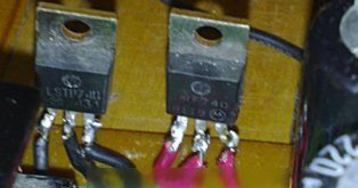
Field-effect transistors - I installed powerful power switches of the IRF740 series with a voltage of 400 Volts at a current of up to 10 Amps, but you can use any other similar switches with an operating voltage of at least 400 Volts with a current of at least 5 Amps.

It is not advisable to add additional measuring instruments to the power supply, since the current here is not entirely constant, and a dial or electronic Voltmeter may not work correctly.
The finished charger is quite compact and lightweight, operates completely silently and does not heat up when idling, and provides a fairly high output current. The costs for components are minimal, but on the market such chargers cost $50-90.
Good day everyone! I’m looking at diagrams on the Internet of switching power supplies and... And I don’t understand! Perhaps the authors don’t read the “Datasheet” for components, or are they specifically discouraged from assembling a UPS??? . Let's look at the description of IR2153: "an improved version of IR2153 -2155, the list of improvements comes down to protection from interference... We read: the recommended load capacitance is 1000 pF, power 0.650 W (short-term)! So this is the data on IR2151!!! And so we have: IR2153 can control keys with a capacitive load of 1n=1000 pf! Look at the "datasheet" of the keys. IR740 - 1450 pf. One and a half times higher than the recommended one. Now the voltage. The recommended maximum voltage of the keys is 600 v (v)! And the keys have 400 v. Well, yes, this more than 310 V! However, everyone who has come across industrial UPS circuits is well aware that switches are placed at a voltage of at least 600 V. Only in Chinese circuits sometimes burnt-out ones at 500 V appear. I hope I explained it clearly?! As for the switch current and resistance key in the open state. This has little effect on the power of the UPS. Let me explain. For a switching power supply, the current is limited by passing through the load and, as a rule, in a pulse does not exceed 2-3 A. In a pulse! We look at the “datasheet” of the keys and see: at a crystal temperature of 100 gr. current with a large margin for the IR740. However, in this case this is a minus for the key! The higher the switch current, the longer the switching time (see the graph there) and, of course, the lower the pulse slope, which means the efficiency is less than the maximum (75%). Accordingly, this key will work, but poorly!!! As a result of the above: this combination leads to burnout of both the keys and the driver! Anyone who wants to repeat this scheme is doomed to a handful of burnt parts! I am wrong? Read the comments on similar diagrams. The question follows: you are so smart, so what do you recommend? I advise everyone who wants to have a simple UPS assembly to take the diagram from the description and recommendation of the IR Company - IR2153 driver with switches for a current of 4-5 A and max. voltage 600-900 V with a control electrode capacitance of no more than 1000 pF. Example STP5NK600C and similar MOSFET triodes. Now about the resistance in the open state for the key: indeed, the greater it is, the stronger the heating of the key. Some will say less efficiency. In this case, the efficiency is not 100% and the effect of resistance is very small. So what affects efficiency? The efficiency is affected by the UPS circuit itself; for an efficiency of up to 94%, we assemble a resonant UPS. Efficiency up to 75% - with the right keys on the IR2153!. Is this efficiency not enough for you? Hm. What about a pulse transformer? How will it limit efficiency? Has anyone already counted? Losses at frequencies above 50 kHz increase significantly, although losses up to 50 kHz are not zero. Let's look at industrial circuits: winding pulse transformers is a very capricious task; two equally wound transformers have different inductances! What is this? And this is what it is! Each IT has its own optimal operating frequency. How do you like this? That's it - read on and look at the UPS diagrams for TVs, powerful amplifiers, and other factory electrical appliances. Good luck to you!
A fairly simple diagram of a laboratory power supply or charger, for example, for a battery. It is implemented quite simply, as can be seen from the diagram. A unique feature of the circuit is the fact that it is possible to adjust not only the voltage, but also the current, which even many commercial chargers do not have.
The circuit is built on 4 transistors, the main role is played by power transistor V4 (see diagram) in this case, 2N3055 is taken, which can easily be replaced with the domestic analogue of KT803. In general, the output power of the device and the possible maximum current will ultimately depend on this transistor, so if you need higher currents, just replace V4 with a more powerful transistor. It is clear that the power transistor must be installed on the heat sink.

Another feature of such a charger is its cost-effectiveness; all the elements will cost you 100-200 rubles. When using the 2N3055 transistor shown in the diagram or its domestic analogue KT803, the current can be accelerated to 6 A. Although the transistor itself, according to its characteristics, can handle 15 A, we do not recommend loading it to such an extent. Limiting resistor R2 with a nominal value of 1 Ohm is taken with a power of at least 5 W, for the remaining resistors 0.25 W is enough.

So far we have considered only the part of the circuit responsible for regulating voltage and current. However, it is clear that the device must be powered with something, especially with a constant voltage, so a power source is needed capable of delivering sufficient output power, with a constant voltage of up to 16 V, and a current of up to 10 A. In principle, for power supply from a 220V, 50 Hz network it was It would be enough to wind up a step-down transformer and put a bridge at its output. However, even a superficial calculation shows that a transformer is needed with a power of up to 200 W.

The core for it can be obtained from old tube TVs, but not everyone has this opportunity, and if you buy it, it will be quite expensive. Plus, using such a circuit will greatly increase the dimensions of the device itself. Therefore, to reduce the dimensions of the transformer, we will use the presented circuit of a switching power supply increasing the frequency to 50 kHz, which ultimately leads to a reduction in the dimensions of the output transformer.

The only thing is that the transformer was taken from a computer power supply designed for bipolar voltage; we understand that one polarity is enough. The ratings and types of elements are indicated in the diagram.

The circuit has short circuit protection; when it is triggered, the LED lights up, which is also very useful when working with a source. When winding an output transformer, the primary winding consists of 37 turns with a wire with a cross-section of at least 0.5 mm?, the secondary winding consists of 6 turns with a cross-section of at least 2.5 mm?, which can be wound with three cores with a wire of 0.8 mm?. The core can be taken from any computer power supply. The diodes of the rectifier bridge at the output must be high-frequency, we recommend taking KD213.

To adjust the limiting current (protection operation), it is enough to change the value of resistor R10; the lower its value, the greater the protection operation current will be and vice versa. All transistors involved in the circuit must be installed on separate heat sinks or isolated from each other.

After the first rectifier bridge, filter capacitors should be rated from 100 to 470 µF with permissible voltage values up to 400 V.
Very powerful car charger up to 50 Amps. We have already talked about various battery chargers more than once. This time will be no exception; we will consider a very powerful charger, which can ultimately produce power up to 600 W with the ability to overclock to 1500 W.
It is clear that with such high powers we cannot do without a switching power supply, otherwise the dimensions of such a device will be unaffordable in weight and size. The circuit is quite simple, shown in the figure below.
Principle of operation in general, it is no different from other switching power supplies that we reviewed earlier. The structure of the work is constructed as follows: the initial mains voltage is filtered, unwanted ripples are removed, then it is rectified and supplied to the switches, which form high-frequency pulses corresponding to their control circuit. Next, the pulse transformer lowers the voltage to the required value and is rectified by a conventional bridge rectifier. In general, everything is simple.
In this case, the role of the key control circuit is played by a master oscillator based on the IR2153 chip. The microcircuit body kit is shown in the diagram.
IRF740 transistors were used as keys; you can also use others; we immediately note that it is the transistors that set the final power of the charger. When using the IRF740, approximately 850 watts of power is guaranteed.
In addition to the filter, a thermistor is also installed at the input to limit the inrush current. The thermistor should be no more than 5 Ohms and designed for a current of up to 5 A. There is also a slight subtlety in the circuit, because at the mains voltage input 50 Hz there are no requirements for diodes, except for the standard ones: there are no reverse voltage (600 V) and current (6-10 A), you can take almost any with the given parameters.

The second bridge installed at the output has one feature related to the fact that high-frequency voltage is supplied from the transformer, therefore, in addition to a reverse voltage of at least 25 V and a reverse current of up to 30 A, it is imperative to use ultra-fast diodes. By the way, it is not necessary to use 4 diodes as the first bridge; you can take a ready-made diode assembly from a computer power supply.

It will be much more convenient to install. Electrolytic capacitors installed after the first bridge must be designed for a voltage of at least 250 V and with a capacity of 470 μF, by the way, they can also be taken from a computer power supply. Everything is also simple with the transformer; you can take it from the same computer power supply, which you don’t even need to rewind.

Naturally, power switches must be installed on the heat sink, because The transistors have no common points; we install them either on different radiators, or isolate them with mica spacers.

To facilitate repair work, it is advisable to install the microcircuit in a special case for its easy removal and replacement; this will greatly facilitate repair and configuration. To check the device after installation, turn it on in idle mode, i.e. without load. In this case, the power switches should not heat up at all. The power of 25 Ohm resistors on the field gates is enough to take 0.5 W.

The resistor installed to power the IR2153 microcircuit can be taken in the range from 47 kOhm to 60 kOhm with a wattage of at least 5 W; it is current-limiting for current protection of the microcircuit. The output capacitors must be selected with a voltage of at least 25 V and a capacity of 1000 μF.
I would like to immediately draw your attention to the fact that the circuit does not have protection against short circuits, polarity reversal, there is no indication of operation, etc. All these shortcomings can be easily corrected, especially since they have been described on our resource more than once.
And I also want to note one point: if you need to repair your car or refill your air conditioner, then there is no problem. There is an excellent company that does this on a professional level and at the same time does everything as if it were for itself.
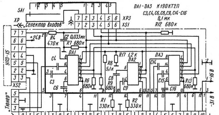
A good and interesting circuit for a high-quality charger based on the IR2153 microcircuit, a self-clocked half-bridge driver, which is often used in electronic ballasts for energy-saving lamps.
The circuit operates from an alternating voltage network of 220 Volts, its output power is about 250 watts, which is about 20 Amperes at 14 Volts of output voltage, which is quite enough to charge car batteries.
There is a surge filter at the input and protection against voltage surges and overload of the power supply. The thermistor protects the keys during the initial moment of turning on the circuit to a 220 Volt network. Then the mains voltage is rectified by a diode bridge.
The voltage passes through a limiting resistance of 47 kOhm to the generator microcircuit. Pulses of a certain frequency follow to the gates of high-voltage switches, which, when triggered, pass voltage into the network winding of the transformer. On the secondary winding we have the voltage required to charge the batteries.
The output voltage of the charger depends on the number of turns in the secondary winding and the operating frequency of the generator. But the frequency should not be raised above 80 kHz, optimally 50-60 kHz.
High voltage switches IRF740 or IRF840. By changing the capacitance of the capacitors in the input circuit, you can increase or decrease the output power of the charger; if necessary, you can reach 600 watt power. But you need 680 uF capacitors and a powerful diode bridge.
The transformer can be taken ready-made from a computer power supply. Or you can do it yourself. The primary winding contains 40 turns of wire with a diameter of 0.8 mm, then we apply a layer of insulation and wind the secondary winding - about 3.5-4 turns of fairly thick wire or use stranded wire.
After the rectifier, a filter capacitor with a capacity of no more than 2000 μF is installed in the circuit.
At the output it is necessary to install pulsed diodes with a current of at least 10-30A, ordinary ones will immediately burn out.
Attention, the charger circuit does not have short circuit protection and will immediately fail if this happens.
Another version of the charger circuit on the IR2153 chip |

The diode bridge consists of any rectifier diodes with a current of at least 2A, or more, and with a reverse voltage of 400 Volts; you can use a ready-made diode bridge from an old computer power supply; it has a reverse voltage of 600 Volts at a current of 6 A.
To ensure the required power parameters of the microcircuit, you need to take a resistance of 45-55 kOhm with a power of 2 watts; if you cannot find such, connect several low-power resistors in series.