Measuring instruments are necessary when working with electrical circuits or networks, because in any other way it is impossible to measure, control, and analyze the technical condition of direct or alternating current circuits, as well as the various consumers connected to them. Such devices include a voltmeter. What kind of device this is, how it works and where it is used, you can find out from this publication, which contains information of interest on the topic. In the article we will tell you how to use a voltmeter and consider the procedure.
Types and types of voltmeters
Unlike a multifunction tester or multimeter, a voltmeter is designed to measure only one quantity - voltage in electrical circuits or in certain sections of them. Despite such a narrow specialization, this device has many varieties according to the principle of operation, purpose and installation method.
According to the principle of operation, devices are divided into:
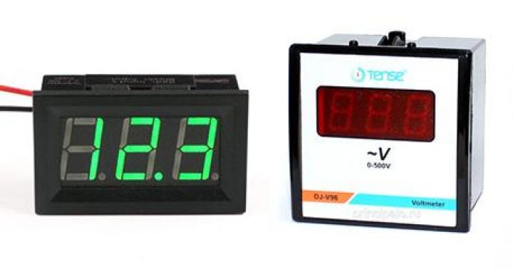
- Electronic, represented by analog and digital models. Visually, they differ in their display panels, which for analog devices look like a scale and arrow, and for digital devices, they look like an electronic display.
 Electronic digital voltmeters transmit the value of the measured quantity to the display
 - Electromechanical, among which the most commonly used are electromagnetic (easy to use and inexpensive to manufacture) and magnetoelectric (rarely found among ordinary electricians, more used in electrical laboratories and research institutions).
 Electromechanical type voltmeter with voltage measuring scale up to 150 V
 Despite their availability, electromagnetic voltmeters have a significant drawback: the high inductance of their own windings, as a result of which the accuracy of the device cannot be called high. Such measuring devices are often used in electrical panels at substations and industrial facilities. Read also the article: → "".
Separation by purpose:
- direct and alternating current – for measuring voltages in the circuits corresponding to the name;
- universal - their circuit allows you to use switches to switch the device to different measurement modes (direct or alternating current);
- pulse – used for measuring periodic pulse signals or single pulses;
- others have special purposes that are not of interest to a wide range of users.
Based on the installation method, you can draw a conclusion based on the names: stationary, panel, portable.
Parameters for assessing the technical characteristics of the device
The voltmeter is connected to the electrical circuit in parallel, so in order not to influence the flow of current in the measurement section, it must have a large internal resistance. The higher this indicator, the more accurate the readings taken and displayed by the device. It’s simple - the current follows the path with the least obstacles, and in order to reduce electricity losses inside the device circuit, it is provided with powerful resistance. If it is connected in series in a circuit, then voltage losses will not allow measurement, and parallel connection will have the opposite effect.
Thus, to evaluate the functionality of the measuring device, the following indicators are taken into account:
- Internal resistance
- The limits of voltages available for measurement by a specific device. Most modern instruments are universal and are capable of displaying values from tenths of a volt to 1 kV, which is quite enough for an electrician, however, there are micro-, millivoltmeters, and kilovoltmeters, which are more often used by specialists and require certain knowledge and skills
 A millivoltmeter is similar in appearance to a voltmeter, but the measurement range is much lower
 - Permissible error, that is, measurement accuracy. This indicator is usually insignificant, but it must be taken into account to establish the actual network voltage.
Practical recommendation: before you start working with a voltmeter, you need to carefully study its characteristics, because if the device is designed for a range of smaller values than the actual voltage in the circuit, it may fail.
To expand the range of measured values, additional resistances can be used. This is done according to the following scheme:
 A simple circuit for connecting additional resistors to expand the permissible measurement limits
 Where Rv is the resistance of the device, UmV is the measurement range of a particular device, Rdob 1-3 are additional resistors, U1, U2, U3 are the modified limits of voltages available for research.
Using a voltmeter at home
Before starting to use the measuring device, you must:
- make sure that this device corresponds to the voltage at which the circuit section is supposed to be located;
- that the device corresponds to the type of voltage (DC or AC) - constant is marked with the sign =, variable is designated ~;
- check that the voltmeter is installed correctly - some pointer models require a certain operating position (vertical or horizontal), about which a corresponding mark is made on the case.
When making measurements in sections of an electrical circuit with a voltage of 60 volts or more, it is recommended to use dielectric rubber gloves and probes with increased insulation. Read also the article: → "".
Adjusting the device settings (adjustment) step by step
For some voltmeters, adjustment is a mandatory procedure before practical use. This applies to analog models with a scale and pointer. As a rule, after inactivity, the needle moves either below zero or above it, as a result of which an error may creep into the instrument readings. To prevent this from happening, it is necessary to make adjustments, namely:
- find the miniature adjustment screw on the front panel of the device;
- using a small flat screwdriver, turn the screw in one direction or the other, ensuring that the arrow is set strictly to “0”;
- Move the device several times to make sure the settings are stable.

Checking and setting the “zero indicator” is a mandatory procedure before each use of an analog model.
Step-by-step instructions for measuring voltage
Measuring voltage in an electrical circuit is carried out in the following order:
- The voltmeter is being prepared for operation. In addition to the steps described above, you need to connect the wires. For this purpose, analog devices have contacts with screws at the top end. Sometimes they have “+” and “-” marks, and wires are screwed to them. For electronic models, the wires are equipped with connectors, and the housing has sockets for them
- The switch on the digital device is set to the “on” position
- On a universal voltmeter, the type of voltage being measured and the range of its values are set. If the value is not known, then in order to avoid overvoltage and failure of the device, the max limit is set, and then gradually lowered until readable values are obtained
- Use probes to make contact with conductors or terminals on the section of the circuit of interest, and the connection should be parallel, as shown in the diagram. There is nothing complicated in this process, the main thing is to carry out all the actions correctly.

Overview of measuring instrument manufacturers
The modern market of measuring instruments is represented by many brands that produce high-quality products with excellent characteristics. Without much difficulty, on the pages of online stores you can find any model of electromechanical or electronic voltmeter you are interested in. As an example, we can cite the products of some brands that have taken a worthy place among manufacturers of measuring equipment from around the world.
| Name of product | Device model | Trademark | Manufacturer country | price, rub. |
| B 7-78/1 | Universal digital voltmeter | AKIP | Russia | 65 895 |
| 34401 A | // | Agilent | USA | 103 600 |
| ABM-4401 | // | Aktakom | Russia | 74 141 |
| GDM-78261 | // | Good Will Instrument Co.,ltd | Taiwan | 73 108 |
These device models have similar technical indicators and work with direct and alternating current circuits in the measured voltage ranges from 1 µV to 750-1000 V. Price values represent average data from online stores in Moscow, are given for comparison and cannot be used for references and compilation estimates
In addition to expensive multifunctional universal instruments, there are many more affordable and no less reliable devices with which you can measure voltage. For example, an analog voltmeter CEC 96 400 V-C-2 from the Circutor S.A. brand. from Spain (price 12,138 rubles) or products from the Voltcraft brand, the cost of which starts from 10,000 rubles. Read also the article: → "".
The user will be able to select a product with the parameters he is interested in in any price segment. However, you need to focus not only on price values, but also on the area of application for which the device is purchased. For most users, for everyday use it will be enough to purchase a “multimeter” tester, which also provides a voltage measurement function. Such products are widely represented by different brands: Ctlsa Messgerate, Proskit, Sturm, UNI-T and others.
Practical recommendation: for use in electrical laboratories, more accurate, but correspondingly expensive, magnetoelectric voltmeters are needed. At various substations and electrical panels, built-in (panel) or stationary models will be more in demand.
The most common mistakes when using a voltmeter
Quite often, when using measuring equipment, due to incorrect actions, situations arise that can lead to electric shock to a person or failure of the device. Below are the mistakes made by users when working with voltmeters.
- Before starting measurements, the section of the circuit to which the voltmeter will be connected is not analyzed. For example, when checking an automation unit with an applied voltage of 18 V at an electromagnetic station, the device is set to the specified value, but during the work it becomes necessary to take measurements on another section of the circuit, flowing with a voltage of 380 V. If you do not adjust the device to the desired value, it may just burn out. Also, the device may fail if you do not switch it according to the type of voltage being measured (DC/AC).
- Due to the similarity in appearance, the voltmeter can be confused and mistaken for an ammeter and connected in series to the electrical circuit. In this case, measurements will not be available, but if you confuse a voltmeter with a millivoltmeter, this can lead to the loss of expensive measuring equipment.
- From prolonged use, the insulation of the wires on the probes of the device may break and the conductor may be exposed. Some users tend to remove the probes altogether and then proceed with the stripped ends of the wire. This is unsafe, especially when operating at voltages greater than 60V, and may result in electric shock. It is better to purchase new probes, which are currently quite available.
- In order to save money, the buyer may be tempted by the low price of a device from an unknown manufacturer, as a result of which he will receive a voltmeter that does not meet the requirements or is completely unsuitable for work. To prevent this from happening, it is better to purchase measuring equipment from well-known brands in specialized stores, while requiring a certificate of conformity and checking for a warranty period (for high-quality products it is at least 12 months).
In conclusion, it is worth noting that voltmeters belong to the popular category of measuring instruments for electrical circuits. Using them is not difficult, but you should not approach this process lightly. It is always necessary to observe caution and safety rules, because electrical circuits and devices are a source of increased danger.
A voltmeter in a car is a rather rare feature. This probably happens because the average motorist is unlikely to often think about voltage, which cannot be said about those who like to keep everything under control... Installing a voltmeter in the car yourself will help you always be aware of the “volts”!
Which voltmeter to choose?
It is extremely difficult to find a car voltmeter, and even a decent looking one, in stores. This happens because such equipment is installed from the factory in literally single cars. If we discard the tuned instruments, then in reality you can only find voltmeters from the VAZ-2107 and UAZ.
The voltmeter from the VAZ “Seven” does not have a housing and this is a huge minus. According to the “statement”, it is attached to the dashboard and “naked” consists of unprotected windings on a small frame and an arrow made of soft metal...
The UAZ voltmeter is a full-fledged device in a sturdy case. The only real negative is the appearance. It is, as befits this car, extremely unpretentious, even military.
The design and quality of the voltmeters considered are unlikely to be suitable for beautiful tuning. Therefore, for those who not only add functionality to their car, but also take into account the interior design of the car, it is better to look for a specialized tuned device.
Connecting a voltmeter to a car
Ideally, the voltmeter should be connected to the positive terminal of the battery - then it will show the most accurate charging voltage. It is required to conduct a wire from the terminal into the interior to the place where the device will be installed. Before starting work, you need to disconnect the battery, take a wire with a cross-section of about 0.5 mm and stretch it into the cabin along the standard wiring harness. It is quite possible that for this you will have to disassemble some of the casings and.
The voltmeter should only work when the ignition is on. When connected directly to the battery terminal, it will be constantly on. You can get around this problem using a conventional electromechanical relay, which is used in abundance in any car.

You can read more about this and that by following the links. Installing a voltmeter in a car follows the same scheme, namely:
— The wire going from the battery to the device is “power” in this case. A relay is installed in its gap, which, when turned off, opens this wire, turning off the voltmeter.
— We take the voltage to the “positive” control contact of the relay from the place where it appears when the ignition is turned on. It could be anything - a mounting block, ignition switch wires, and so on.
— We connect the “minus” of the voltmeter and the second control contact of the relay to “ground”, that is, we screw it to the body with a standard one.
Now, when you turn on the ignition, the installed relay will operate, connect the voltmeter, and it, in turn, will show the number of volts in the on-board network.
Voltmeter protection and backlight

At this point, installing a voltmeter in a car may be completed, but ideally two more steps need to be performed - one for safety, and the second for comfort.
To protect the voltmeter's power circuit from, it is necessary to install a fuse on the wire coming from the battery. This is very simple to do, just cut this wire, like a “mother”, in a suitable place and put them on the terminals of the fuse box. Its rating should be small, for example, 5A (More details about fuse ratings -). The terminals, and for reliability, the fuse itself are better.
And finally, the final step is to illuminate the voltmeter. All devices that are placed in the housing must have it. It is necessary to extend the wire to the backlight contact from where the voltage appears when the side lights are turned on. The “minus” of the backlight, as a rule, is combined with the common negative terminal of the device, and in our case it is already connected to the car body.
Thus, by running just one additional wire, we will get not only a working voltmeter, but also illumination of its scale.
P.S. You need to connect a voltmeter to the battery terminal so that it shows the most accurate voltage. If special accuracy is not required, you can connect the device to any wire in the car interior, on which voltage appears when the ignition is turned on. This is much simpler and faster, does not require the installation of a relay and a fuse, since the electrical circuit is protected by default by a factory “protector”.
With this connection, the voltmeter readings will be slightly lower than in the method discussed in detail above, because on the way from the battery to the passenger compartment, the voltage may decrease due to the large number of different contacts and the resistance on them.
You can connect a voltmeter on an A4 sheet.
Print it out and take it with you.
File size 1.5 MB, jpg format.
Do-it-yourselfers, designing, developing and implementing a variety of charger or power supply circuits, are constantly faced with an important factor - visual monitoring of the output voltage and current consumption. Here Aliexpress very often lends a helping hand, promptly supplying Chinese digital measuring instruments. In particular: a digital ampere-voltmeter is a very simple device, affordable and displays quite accurate information data.
But for beginners, commissioning (connecting an ampere-voltmeter to the circuit) can be a problematic task, since the measuring device comes without documentation and not everyone can quickly connect the color-coded wires.
An image of one of the most popular voltammeters among homemade people is posted below,

This is a 100 volt/10 amp ampere-voltmeter and comes with a built-in shunt. Many radio amateurs quite often purchase such measuring instruments for their homemade products. A digital device can be powered either from separate sources,
and from one operated and measured voltage source. But there is a small nuance hidden here; the condition must be met - the voltage of the power source used was within 4.5-30 V.

For DIYers who still don’t quite understand: connect the thick black wire to the minus of the power supply, the thick red wire to the plus of the power supply (the voltmeter scale readings will light up),

We connect a thick blue wire to the load, the second end from the load goes to the plus of the power supply (the ammeter scale readings will light up).

Faced with the need to find out the voltage value in a section of an electrical circuit, many people ask the question: how to connect a voltmeter? It's very simple, but you need to know a few simple rules.
This device is a measuring device. It is used to count, measure voltage and electromotive force in electrical networks. It is connected in parallel to the load or power source.
Main characteristics of the device
Knowing its structure and operating principles will help you connect the voltmeter correctly. The type of ordinary portable voltmeter is known to everyone. This is a rectangular box with a front screen, levers, buttons and connectors for contacts. It is equipped with a handle on which it can be placed in a raised position, and it also serves to carry it. There are also very compact options that look like an ammeter. It's just a small box with terminals and a scale with an arrow.
Some devices similar to an ammeter can be identified by the V sign on the display. In diagrams it is depicted with the same letter, but in a circle. Just like the first one, it has a “+” sign at one end. It must be connected to the positive end of the source, that is, to the point with the positive value of the circuit. Otherwise, the pointer will point in the opposite direction to the correct direction.

The greater the resistance inside the device, the better, since in this case the resistance has the least influence on the object being measured, so its readings are more accurate and the range of application is wider.
There are quite a varied number of modifications:
- according to the operating principle (electromechanical, static, electronic);
- by purpose (pulse, direct/alternating current, phase-sensitive, selective, universal);
- stationary, panel, portable.
A more technical definition of a voltmeter is: a galvanometer with high sensitivity, significant resistance, equipped with a display that displays the potential difference, or electrical excitation value in volts.
Return to contents
The principle of operation of a voltmeter
It measures a variety of current values flowing through the device. The operating principle is the same for all devices, but the design can be very diverse.

Some of these outdated devices consist of a coil of thin wire, it is located between the ends of a magnet in the shape of a horseshoe with an iron arrow that moves on an axis. Current flows in this coil. The magnetized pointer moves depending on the current strength: the stronger it is, the greater its deviation (that is, the more significant the potential difference between the ends of the coil wire).
Some do not have magnets; the current passes through the coil, drawing a thin metal tube inside; in other words, it moves a metal cylinder located on the axis relative to the coil.
In devices designed for alternating current, current is passed through a wire installed in a special way, causing it to heat up, thereby changing its size, which is displayed by the indicator.
When taking measurements, it is necessary to take into account the heating resistance and calculate the correction, so some devices are already designed in such a way as to measure with a correction.
Return to contents
The first thing you need to know is that if you connect a device to a circuit in a series manner, it may fail.
Parallel connection is used because it reduces current.

The voltmeter is connected in such a way that its powerful resistance does not change the measurement readings. When connected in series, the current power in the circuit will be minimal.
Correctly, the device is connected to the circuit in parallel to its part: this way it does not affect the flow of currents, and therefore a large resistance is required. Do not confuse a voltmeter with an ammeter, which is connected in series, because there should be a minimum resistance in it.
The current that flows through the device is much less than that flowing through the area of the circuit being tested. There are no influencing forces within it. The difference between the ends of the terminals is the same as the voltage, so it measures it.
The device connection looks like this. To measure the voltage that exists between two selected points in an electrical circuit, you simply need to connect it to them so that such a connection is parallel to the power source. The voltmeter has virtually no effect on the current due to its passage through itself, since it is created specifically for this purpose with significant resistance. Therefore it does not cause any loss of energy.
In order to expand the measurement range, an additional resistor is mounted in series with the winding of the device. In this case, only part of the measured current goes to the meter; it is proportional to the resistance of the device. With a known resistor value, the voltage indicator is determined using a voltmeter.
Such a resistor is built inside the device; it is simultaneously used to reduce the influence of ambient temperatures on the voltmeter readings. To do this, it is made of a material with a low temperature coefficient, its resistance is less than that of the coil, and therefore the total resistance of the device is almost independent of temperature.
How to connect a voltmeter?

In any modern car with an on-board computer, you can find out the voltage of the on-board network. But what should car enthusiasts who do not have a car with an on-board computer do? To do this, you can install the voltmeter yourself, it’s not difficult.
The question arises, why even know the voltage of the on-board network? The fact is that the machine is a large consumer of electricity during its operation. And in order for energy not only to be spent, but also to accumulate in the battery, you need to have a voltage in the on-board network higher than at the battery terminals. How to connect a voltmeter?
Connecting a voltmeter
The voltmeter is connected to the network in parallel. Since the entire car body is “minus”, the negative terminal can be connected to any point of “ground”. And it makes sense to connect the positive wire to the “plus” of the generator so that you can know the voltage produced by the generator. This is usually 14 volts.
Wires for connection should be chosen with a thicker cross-section so that there are no errors in determining the voltage. It is also necessary to install a fuse in the circuit if it is not provided in the voltmeter itself.