The use of an ABS sensor is associated with its inductive properties (the sensor itself is an induction coil and a gear ring). Due to these properties, the sensor can read the pulses, transmitting them to the control unit. The control unit is responsible for the proper functioning of the hydraulics, and, receiving information from the sensor, regulates the pressure of the oil in the brake system. The ABS sensor, like other vehicle sensors, may one day fail and the ABS sensor will need to be checked - this is a common procedure that must be performed periodically.
The most common problem that happens with the ABS sensor is a violation of the circuit connecting the sensor to the control unit, as well as a breakdown of the sensor - these problems begin to distort the information received and transmit false data to the control unit.
Violation of anti-lock, at the same time, are detected while driving, as well as by a burning ABS light located on the dashboard. The exact cause of the breakdown can only be determined after a thorough diagnosis.
The first actions of the driver when the ABS lamp is on
Of course, a tanned control light forces, first of all, to check the ABS sensor. You can do this without contacting a car service. At the same time, for a correct check, the car owner will need a multimeter, an operating manual for the car, wiring with PIN connectors. Yes, you can't do without an extra pair of hands.
How to check resistance
The multimeter works in ohmmeter mode
- Using a jack or lift, raise the car;
- We dismantle the wheel (if, in your car model, it is an obstacle on the way to the sensor);
- We twist the screw fixing the sensor (it is located behind the hub);
- We dismantle the casing that protects the ABS control unit, after which we disconnect all connectors going to the controllers;
- We include wiring with PIN connectors in the circuit, connecting them to the multimeter and to the sensor;
- We measure the resistance, referring to the normative data from the instruction manual;
- We carry out a wiring check to exclude the possibility of its short circuit.
Using the help of a partner, you need to manually, several times, spin the wheel, fixing the resistance indicators. When changing the rotation speed, the instrument readings should also change.
For a working ABS sensor, the multimeter will have the following indicators:
- For the sensor-leg circuit: 5-26 ohms;
- For the sensor-to-ground circuit (circuit insulation test): at least 20,000 ohms.
How to check voltage
The multimeter works in voltmeter mode
- We raise the car on a jack, hanging its wheels;
- PIN connectors of pre-prepared wiring are connected to the multimeter contact;
- We begin to rotate the wheel, trying to maintain the rotational speed at the level of 1 revolution per second;
During normal operation of the sensor, the readings of the voltmeter will be in the range from 0.25 Volts to 1.2 Volts. Please note that increasing the wheel speed will increase the meter reading.
Additional diagnostic options
You can also check the ABS sensor using an oscilloscope that measures the amplitude and resistance indicators. However, an oscilloscope is very expensive, and it is much more difficult to use it than a multimeter.
Another way to understand what exactly broke down when the ABS lamp was on is to decipher the information that the anti-lock braking system on new cars represents. As soon as such a system is activated, it displays coded errors on the on-board computer screen of the car. It is not difficult to decipher such errors, it is enough to study the operating manual of the machine, or find information on the error code on the Internet.
Attention! When checking the ABS sensor and connecting the multimeter wires to it, you must observe the polarity. This is described in detail in the Vehicle Operation Manual: in particular, the color markers of the wires are described there and all the connectors are indicated.
Only after a thorough check of the operation of the ABS sensor, you can proceed to its repair or replacement. Repair means soldering the damaged ABS sensor wiring and protecting the wire connections with a layer of electrical tape.
Video: Checking the ABS sensor
If the video is not showing, refresh the page or
Describe the problem in its entirety!
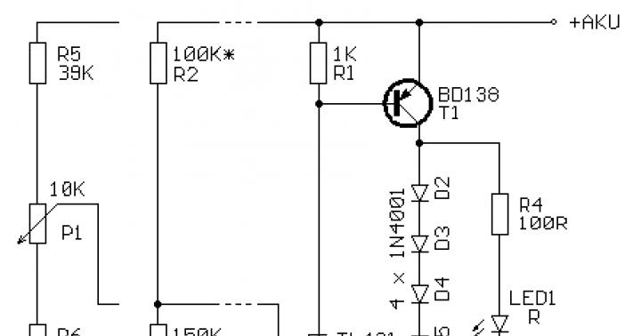
This winter, I encountered the fact that the battery ran out several times during the night, the reason for this was the ABS unit spontaneously turning on (!!!) when it pleases (!!!) when the ignition switch is completely turned off (by the way, I found a bunch of cases on forums when people talk about an incomprehensible hum from the front left under the hood, and so, this is the ABS pump buzzing) and this is most likely a factory flaw (defect) "constant power supply to the consumer." I’ll clarify right away that I don’t have a “sticky” ABS relay near the right pillar, according to the diagram, it shouldn’t be there on the restyling! I will add that in normal mode, the anti-lock worked flawlessly.My ABS Schematic:
As we can see there is no relay!!!In order to prevent the battery from landing, I simply pulled out the power fuse (near the battery, it seems to be 20 amps) and did not bathe until the technical inspection was passed ... at which they said that if there is ABS, then serviceability is required! I insert the fuse without hesitation and see that the ABS lamp on the instrument panel does not go out, the ABS pump is already buzzing CONSTANTLY and of course the wheels go skidding when braking. Of course, I didn’t pass the inspection in that company for the above reason, but I passed it in another, not the point, but the loss of 750 rubles ... After that, I forgot about ABS again - summer)), but it wasn’t there! The other day, for no apparent reason, I get into the car during the day, start it up and see that I have a burning parking brake lamp added to the ABS lamp (it’s the brake level), well, I think the pads are worn out, the level has dropped, but to my surprise, the level is normal, the handbrake removed, the problems are growing)). But that's not all, after starting to move, I see that my speedometer and 4WD do not plow ... Zhzhzhzhzhzhzhest ... I'm just at a loss ... Multitronics gave errors (1000 and 1001 - can-bus - were from the moment the car was purchased) and (0110 - intake air temperature sensor and 0500 - speed sensor are new errors)
Troubleshooting:
I rang all the ABS sensors on the wheels - they ring only in one direction and have a resistance of 605-620 Ohm, they have no visible damage. I replaced the ABS block because when removing the connector from the old one, I felt a sharp smell of burnt wiring (microcircuit) after removal, this was confirmed, but until my hands reached to disassemble the half of the block with the microcircuit. And an important point: after the ABS block was halved, condensate was present on the inner surface of the parts, which possibly caused the failure of this unit.The ABS block (used) cost me 4,000 rubles (for information, the price of a new block on the existential is !!! 105711 !!! rubles) searching for it was difficult although dorestaylingovyh blocks darkness.
Installing a new block did absolutely nothing. No changes.
The search for consult diagnostics was not successful, only European (left-hand drive) models not older than 2008 are diagnosed for officials, I went to two diagnosticians to enter their devices to enter the ABS diagnostic mode, for some reason they cannot understand, although the engine scanners enter the diagnostic mode without problems !
The car also refuses to enter the self-diagnosis mode! In the ABS diagnostic mode too! Ambush!
I don’t know what to do, and therefore I created a detailed topic so that in the future the users of this car will solve similar problems once or twice))
Help out guys! What are the main thoughts?
P.s. The fuses on both pads (under the hood and in the cabin are intact) was one burned out on 4WD, you can see with the old ABS block shorted.
Vehicle:Nissan X-Trail
Release year:2004
Complete set: QR-20, NT-30 automatic, restyling
A modern injection engine is controlled by many sensors. Only the electronic system that controls the actions of the motor does not always cause a breakdown. How to check the sensors of an injection car - the health of the sensors must be constantly checked, evaluating the performance of parts and components of the power unit. Only the Check Engine lamp indicates a sensor malfunction; it lights up on the parting panel.
To check the sensors, we need: an ohmmeter (multimeter), a dismantling tool.
The throttle position sensor is a variable resistor. Checking its functionality, we measure the resistance between its conclusions.
The readings obtained must be compared with the factory values \u200b\u200bthat are indicated in the instructions. Normally, if the discrepancy is 20 percent.
Another indication of a sensor malfunction is idle instability, possible jumps in the process of increasing speed.
It is not possible to test the knock sensor, specialized equipment must be on hand. There is an indirect sign of a breakdown of the device - this is increased detonation at the time of engine operation. To carry out diagnostics and replacement of the sensor, it is necessary to contact specialists.
The same situation is with the timing sensor. It is mounted on engine units with four valves, directly on the cylinder. To check, you will need special diagnostic tools.
Maybe the car's engine won't start. This means that the crankshaft position sensor is faulty. There is one such sensor that does not turn on if the motor breaks down. To carry out an additional check, we measure the resistance between the terminals, and disconnect the connector in advance. The parameters of this indicator should not exceed 750 ohms.
Sometimes the cause of the breakdown of the crankshaft position sensor is the controller, which is present on the crankshaft pulley disk. The rubber damper, placed on the gear wheel of this controller, is capable of turning relative to the pulley.
It is necessary to find marks on the camshaft, flywheel. It must be remembered that the mark on the flywheel still duplicates the mark present on the crankshaft. The roller is installed correctly, which means that these marks will match.
How to check the sensors of an injection car, in order to assess the suitability for the operation of the sensor responsible for the mass air flow, the wiring block that fits it must be disconnected. Now we measure the resistance between the output according to the indicated control system diagram. Usually, this indicator does not exceed the value of 6 kOhm.
You can remove the sensor from a running engine. The engine will not slow down less than 1500 rpm. There is also a sign of a malfunction of such a sensor - unstable engine operation, difficult starting of the power unit, jumps, delays, dips during movement, traction and power are insufficient.
In order to assess the health of the speed sensor, you should switch to neutral gear when the machine is idling. If the sensor is working, then the speed will increase slightly. On some cars, if the sensor is faulty, the speedometer stops functioning.
How to check the sensors of an injection car - to check the sensor responsible for the temperature of the coolant, you should find a special table in the documentation. Any change in temperature in this system must be accompanied by deviations in the resistance of the sensor.
We check the oxygen sensor by measuring the resistance of the heater, having previously disconnected the connector from it. The result varies from 0.5 ohms, the limit is 10 ohms, it all depends on the device model. More detailed information is recorded in the instructions. To check, remove the connector from the sensor, turn on the ignition, check the reference voltage of the present controller, its parameter is 0.45 V.
How to check the sensors of an injection car - difficult? Then to the car service!
We watch the video - how to change the phase sensor on the Lada Kalina on an eight-valve engine
Liked the article? Share with your friends on social networks!
The presence of ABS in the vehicle at times increases traffic safety. Gradually, car parts wear out and may become unusable. Knowing how to check the ABS sensor, the driver can identify and fix the problem in time without resorting to the services of a car repair shop.
How ABS works in a car
Anti-lock braking system (ABS, ABS; English. Anti-lock braking system) is designed to prevent blocking of the car wheels.
The primary task of ABS is preservation control over the machine, its stability and controllability during unforeseen braking. This allows the driver to make a sharp maneuver, which significantly increases the active safety of the vehicle.
Since the coefficient of friction is reduced in relation to the coefficient of rest, the car will cover a much greater distance when braking on locked wheels than on rotating ones. In addition, when the wheels are blocked, the car carries a skid, depriving the driver of the chance to carry out any maneuver.
The ABS system is not always effective. On an unstable surface (loose soil, gravel, snow or sand), immobilized wheels form a barrier from the surface in front of them, breaking into it. This significantly reduces the braking distance.A car with studded tires on ice when the ABS is activated travels a greater distance than with locked wheels. This is due to the fact that the rotation prevents the spikes, crashing into the ice, from slowing down the movement of vehicles. But at the same time, the car retains controllability and stability, which in most cases is much more important.
Wheel speed sensors mounted on the hubs
The equipment installed on individual vehicles allows the function of disabling the ABS.
This is interesting! Experienced drivers on cars that are not equipped with an anti-lock device, when unexpectedly braking on a difficult section of the road (wet asphalt, ice, snow slurry), act on the brake pedal jerkily. In this way, they avoid complete wheel lockup and prevent the car from skidding.
ABS device
The anti-lock device consists of several nodes:
- Speed meters (acceleration, deceleration);
- Control magnetic shutters, which are part of the pressure modulator and located in the line of the braking system;
- Electronic monitoring and control system.
The pulses from the sensors are sent to the control unit. In the event of an unexpected decrease in speed or a complete stop (blockage) of any wheel, the block sends a command to the desired damper, which lowers the pressure of the fluid that enters the caliper. Thus, the brake pads are weakened, and the wheel resumes movement. When the wheel speed equalizes with the rest, the valve closes and the pressure in the entire system equalizes.

General view of the ABS system in the car
On newer vehicles, the anti-lock braking system is triggered up to 20 times per second.
The ABS of some vehicles includes a pump, the function of which is to quickly increase the pressure in the desired section of the highway to normal.
This is interesting! The action of the anti-lock braking system is felt by reverse shocks (blows) on the brake pedal with strong pressure on it.
By the number of valves and sensors, the device is divided into:
- Single channel. The sensor is located near the differential on the rear axle. If even one wheel stops, the valve lowers the pressure on the entire line. Found only on older cars.
- Dual channel. Two sensors are located on the front and rear wheels diagonally. One valve is connected to the line of each bridge. It is not used in cars manufactured according to modern standards.
- Three-channel. Speed meters are located on the front wheels and rear axle differential. Each has a separate valve. It is used in budget rear-wheel drive models.
- Four-channel. Each wheel is equipped with a sensor and its rotation speed is controlled by a separate valve. Installed on modern cars.
Main types
ABS sensor with is read by the paramount measuring part of the anti-lock braking system.
The device consists of:
- A meter placed permanently near the wheel;
- Induction ring (rotation indicator, impulse rotor) mounted on the wheel (hub, hub bearing, CV joint).
Sensors are available in two versions:
- Straight (end) cylindrical shape (rod) with an impulse element at one end and a connector at the other;
- Angled with a connector on the side and a metal or plastic bracket with a hole for a mounting bolt.
There are two types of sensors available:
- Passive - inductive;
- Active - magnetoresistive and based on the Hall element.

Passive
They are distinguished by a simple system of work, while they are quite reliable and have a long service life. Does not need to be connected to power.An inductive sensor is essentially an induction coil made of copper wire, in the middle of which is a stationary magnet with a metal core.
The meter is located with its core to the impulse rotor in the form of a wheel with teeth. There is a certain gap between them. The teeth of the rotor are rectangular in shape. The gap between them is equal to or slightly more than the width of the tooth.
While the transport is in motion, as the teeth of the rotor pass near the core, the magnetic field penetrating through the coil is constantly changing, forming an alternating current in the coil. The frequency and amplitude of the current are directly dependent on the speed of the wheel. Based on the processing of this data, the control unit issues a command to the solenoid valves.
The disadvantages of passive sensors are:
- Relatively large dimensions;
- Weak accuracy of indications;
- They begin to function when the car speeds up more than 5 km / h;
- They work with minimal rotation of the wheel.
Due to frequent errors on modern cars, they are extremely rarely installed.
magnetoresistive
The work is based on the property of ferromagnetic materials to change electrical resistance when exposed to a constant magnetic field.
The part of the sensor that controls changes is made of two or four layers of iron-nickel plates with conductors deposited on them. Part of the element is installed in an integrated circuit that reads changes in resistance and forms a control signal.
The impulse rotor, which is a magnetized plastic ring in places, is rigidly fixed to the wheel hub. During operation, the magnetized sections of the rotor change the medium in the plates of the sensitive element, which is fixed by the circuit. At its output, pulse digital signals are generated that enter the control unit.
This type of device controls the speed, the course of rotation of the wheels and the moment of their complete stop.
Magneto-resistive sensors detect the change in the rotation of the vehicle's wheels with great accuracy, increasing the effectiveness of safety systems.
Based on the Hall element
This type of ABS sensor operates based on the Hall effect. In a flat conductor placed in a magnetic field, a transverse potential difference is formed.

Hall effect - the appearance of a transverse potential difference when a conductor with direct current is placed in a magnetic field
This conductor is a square-shaped metal plate placed in a microcircuit, which includes a Hall integrated circuit and a control electronic system.The sensor is located on the opposite side of the impulse rotor and has the form of a metal wheel with teeth or a plastic ring in places magnetized, rigidly fixed to the wheel hub.
The Hall circuit continuously generates signal bursts of a certain frequency. At rest, the frequency of the signal is reduced to a minimum or stops completely. During movement, magnetized areas or teeth of the rotor passing by the sensing element cause current changes in the sensor, fixed by the tracking circuit. Based on the received data, an output signal is generated that enters the control unit.
Sensors of this type measure the speed from the beginning of the movement of the machine, they are distinguished by the accuracy of measurements and the reliability of functions.
Causes and symptoms of malfunctions
In new generation cars, when the ignition is turned on, an automatic self-diagnosis of the anti-lock braking system takes place, during which the performance of all its elements is assessed.
signs | Possible reasons |
Self-diagnosis shows an error. ABS is disabled. | Incorrect operation of the control unit. Break in the wire from the sensor to the control unit. |
Diagnostics does not find errors. ABS is disabled. | Violation of the integrity of the wiring from the control unit to the sensor (break, short circuit, oxidation). |
Self-diagnosis gives an error. ABS works without turning off. | Break in the wire of one of the sensors. |
ABS does not turn on. | Break in the power supply wire of the control unit. Chips and fractures of the impulse ring. Lots of play on a worn hub bearing. |
In addition to the display of light indications on the dashboard, the following signs of a malfunction of the ABS system exist:
- When pressing the brake pedal, there is no reverse knocking and vibration of the pedal;
- During emergency braking, all wheels are blocked;
- The speedometer needle shows a speed less than the actual speed or does not move at all;
- If more than two gauges fail, the parking brake indicator lights up on the instrument panel.

In the event of a malfunction of the anti-lock braking system, a warning lamp lights up on the dashboard
The reasons for the inefficient operation of the ABS can be:
- Failure of one or more speed sensors;
- Damage to the wiring of the sensors, which entails unstable signal transmission to the control module;
- A voltage drop at the battery terminals below 10.5 V leads to the shutdown of the ABS system.
How to check the ABS sensor
You can check the health of the speed sensor by contacting a car service specialist, or by yourself:
- Without special devices;
- multimeter;
- Oscilloscope.
Tester (multimeter)
In addition to the measuring device, you will need a description of the functionality of this model.The sequence of work performed:
- The car is installed on a platform with a smooth, uniform surface, fixing its position.
- The wheel is dismantled for free access to the sensor.
- The plug used for connection is disconnected from the general wiring and cleaned of dirt. The rear wheel connectors are located at the rear of the passenger compartment. To ensure unhindered access to them, you need to remove the rear seat cushion and move the carpet with soundproofing mats.
- Conduct a visual inspection of the connecting wires for the absence of abrasions, breaks and violation of the insulation.
- The multimeter is set to ohmmeter mode.
- The sensor contacts are connected to the probes of the device and the resistance is measured. The rate of indications can be found in the instructions. If there is no reference book, then readings from 0.5 to 2 kOhm are taken as the norm.
- The wiring harness must be ringed in order to exclude the possibility of a short circuit.
- To confirm that the sensor is working, scroll the wheel and monitor the data from the device. The resistance reading changes as the rotation speed increases or decreases.
- Switch the instrument to voltmeter mode.
- When the wheel moves at a speed of 1 rpm, the voltage should be 0.25-0.5 V. As the rotation speed increases, the voltage should increase.
- Observing the stages, check the remaining sensors.
It is important! The design and resistance values of the sensors on the front and rear axles are different.

Resistance from 0.5 to 2 kOhm at the ABS sensor terminals is considered optimal
According to the measured resistance indicators, the operability of the sensors is determined:
- The indicator is reduced compared to the norm - the sensor is faulty;
- The resistance tends or corresponds to zero - interturn short circuit in the induction coil;
- Change of resistance data when bending the wiring harness - damage to the wire strands;
- The resistance tends to infinity - a wire break in the sensor harness or induction coil.
It is important! If, after checking the functions of all sensors, the resistance index of any of them differs significantly, this sensor is faulty.
Before checking the wiring for integrity, you need to find out the pinout of the control module plug. After that:
- Open the connections of the sensors and the control unit;
- According to the pinout, all the wire harnesses ring in turn.
The device allows you to more accurately determine the performance of the ABS sensor. According to the graph of the signal change, the magnitude of the pulses and their amplitude are tested.Diagnostics is carried out on a car without removing the system:
- Disconnect the device connector and clean it of dirt.
- The oscilloscope is connected to the sensor through the pins.
- The hub is rotated at a speed of 2-3 rpm.
- Fix the signal change schedule.
- In the same way, check the sensor on the other side of the axle.

The oscilloscope gives the most complete picture of the operation of the anti-lock braking system sensor
Sensors are OK if:
- The recorded amplitudes of signal fluctuations on the sensors of one axis are identical;
- The graph curve is uniform, without visible deviations;
- The amplitude height is stable and does not exceed 0.5 V.
Without appliances
The correct operation of the sensor can be determined by the presence of a magnetic field. Why any object made of steel is applied to the sensor body. When the ignition is turned on, it should be attracted.
In addition, it is necessary to inspect the sensor housing for its integrity. Wiring should not show scuffs, insulation breaks, oxides.The connecting plug of the sensor must be clean, the contacts are not oxidized.
It is important! Dirt and oxides on the contacts of the plug can cause distortion of the signal transmission.
Sensor repair
A failed passive ABS sensor can be repaired by yourself. This requires perseverance and mastery of tools. If you doubt your own abilities, it is recommended to replace the faulty sensor with a new one.
Repair is carried out in the following sequence:
- The sensor is carefully removed from the hub. The soured fixing bolt is unscrewed, having previously been treated with WD40 liquid.
- The protective case of the coil is sawn with a saw, trying not to damage the winding.
- The protective film is removed from the winding with a knife.
- The damaged wire is unwound from the coil. The ferrite core is shaped like a spool of thread.
- For a new winding, you can use copper wire from RES-8 coils. The wire is wound so that it does not protrude beyond the dimensions of the core.
- Measure the resistance of the new coil. It must match the parameter of a working sensor located on the other side of the axle. Lower the value by unwinding a few turns of wire from the spool. To increase the resistance, you will have to rewind the wire of greater length. Fix the wire with adhesive tape or tape.
- Wires, preferably stranded, are soldered to the ends of the winding to connect the coil to the bundle.
- The coil is placed in the old housing. If it is damaged, then the coil is filled with epoxy resin, having previously placed it in the center of the housing from the capacitor. It is necessary to fill the entire gap between the coil and the walls of the condenser with glue so that air voids do not form. After the resin has hardened, the body is removed.
- The sensor mount is fixed with epoxy resin. It also treats the cracks and voids that have arisen.
- The body is brought to the required size with a file and sandpaper.
- The repaired sensor is installed in its original place. The gap between the tip and the gear rotor with the help of gaskets is set within 0.9-1.1 mm.
After installing the repaired sensor, the ABS system is diagnosed at different speeds. Sometimes, before stopping, spontaneous operation of the system occurs. In this case, the working gap of the sensor is corrected with the help of spacers or grinding of the core.
It is important! Faulty active speed sensors cannot be repaired and must be replaced with new ones.
Video: how to repair an ABS sensor
Wiring repair
Damaged wiring can be replaced. For this:
- Disconnect the wire plug from the control unit.
- Draw or photograph the layout of the wiring brackets with distance measurements.
- Unscrew the mounting bolt and dismantle the sensor with wiring, after removing the mounting brackets from it.
- Cut off the damaged section of the wire, taking into account the length margin for soldering.
- Remove protective covers and staples from the cut cable.
- Covers and fasteners are put on a wire pre-selected according to the outer diameter and cross section with a soapy solution.
- Solder the sensor and connector to the ends of the new harness.
- Isolate soldering points. The accuracy of the signals transmitted by the sensor and the service life of the repaired wiring section depend on the quality of the insulation.
- The sensor is installed in place, the wiring is positioned and fixed according to the diagram.
- Check the operation of the system in different speed modes.

The soldering point must be insulated with high quality to increase the accuracy of the transmitted signals
The safety of road users depends on the efficiency of the anti-lock braking system. If desired, the diagnosis and repair of ABS sensors can be carried out independently, without resorting to the services of a car service.
A modern car is made up of many mechanical, electromechanical and electronic components. Optimal operation of the engine must be ensured regardless of external conditions. When external factors change, the operation of nodes and components must adapt to them. Vehicle sensors serve as a kind of tracking device for the operation of the car. Consider the main sensors:
3. Air flow sensor in a car - what does it affect?
 The principle of operation of the air flow sensor is based on measuring the amount of heat given off to the air flow in the engine intake manifold. Heating
the sensor element is installed in front of the vehicle's air filter. Change
air flow rate and, accordingly, its mass fraction, is reflected in the degree
changes in the temperature of the heating coil of the MAF sensor.
"Tripling" of the engine during operation and loss of power indicates a possible failure of the air flow sensor.
4. Oxygen sensor, lambda probe - sensor malfunction

An oxygen sensor or lambda probe detects the amount of oxygen left in the exhaust manifold after fuel combustion. The lambda probe is part of the electronic engine management system, which regulates the amount of fuel, ensuring its complete combustion. Increased fuel consumption characterizes a possible sensor malfunction.
5. Throttle sensor - symptoms of malfunction
 This sensor is an electromechanical device consisting of a sensing element and a stepper motor.
The sensitive element is
temperature sensor, and the stepper motor is the actuator.
This electromechanical device changes the position of the throttle valve
relative to the coolant temperature. Thus, the rotation frequency
crankshaft of the engine depends on the degree of heating of the coolant.
A characteristic symptom of a malfunction of this sensor is the lack of warm-up speed and increased fuel consumption.
6. Oil pressure sensor - functions, failure
On cars of the Japanese brand, a diaphragm oil pressure sensor is installed
type. The sensor consists of two cavities separated by a flexible membrane. Oil
acts on the membrane on one side, bending from pressure. In the measuring
The membrane of the sensor cavity is connected to the rheostat rod.

Depending on the engine oil pressure, the diaphragm flexes more or less, changing the overall resistance of the sensor. The oil pressure sensor is located on the engine block.
A burning oil pressure light on the car panel may indicate a sensor failure.
7. Is the knock sensor in the engine not working?
 The engine knock sensor measures the ignition timing. During normal engine operation, the sensor is in "idle" mode. When the process changes
combustion in the direction of the explosive nature of the combustion of fuel-detonation, the sensor sends a signal to the electronic engine control system to change the advance angle
ignition in the direction of decreasing.
It is located in the air filter area on the cylinder block. To check the performance of the knock sensor, you must run.
8. Camshaft angle sensor - troit engine
 This sensor is located on the cylinder head and measures the engine speed.
camshaft of the engine, and based on the signals from the sensor, the control unit determines the current position of the pistons in the cylinders.
Uneven engine operation and tripling indicate incorrect operation of the sensor. The check is carried out using an ohmmeter, measuring the resistance between the sensor terminals.
9. ABS / ABS sensor in the car - check the performance
 Electromagnetic type ABS sensors are installed on the wheels of the car and are part of the car's anti-lock braking system.
Sensor function is the measurement of wheel speed. The object of measurement of the sensor is the signal gear disk, which is mounted on the wheel hub. If the ABS sensor is faulty, the control light on the control panel does not go out after starting the engine.
The technology for determining the operability of the sensor is to measure the resistance between the contacts of the sensor; in case of a malfunction, the resistance is zero.
10. Fuel level sensor in a car - how to check if it works?
The fuel level sensor is installed in the fuel pump housing and consists of several components. The float, through a long rod, acts on a sector rheostat, which changes the resistance of the sensor depending on the fuel level in the car's tank. The sensor signals are sent to a pointer or electronic pointer on the vehicle control panel. Checking the performance of the fuel level sensor is carried out with an ohmmeter, which measures the resistance between the sensor contacts.