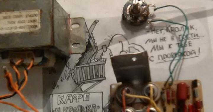
They gave me some kind of incomprehensible block from Soviet times. The schematic resembled some kind of power regulator or something. In itself, it was of no value, but I really wanted to adapt the KU202 it contained somewhere.
I would like to present to your attention a small experiment with phase-pulse charging. The long-known scheme was taken as a basis
The purpose of the experiment is to make the circuit more reliable and practical.
The circuit also fits well with this charger


How many rubles will such a charger cost?
KU202 80*2=160
BD140/139 15*2=26
Diodes D4/5/8 3*5=15
Diodes D1/2 2*100=200
Resistors 9*3=27
Potentiometer 60
Capacitor 20
Textolite 50
And that’s 558R plus a 1500R transformer and, if desired, an ammeter +500R.
It's good when you have something of your own. For this scheme as a whole, I paid 300 RUR, purchasing additional change.
Charging on KU202 is just an experiment. For safe, high-quality and reliable charging of any types of batteries, I recommend this
With uv. Admin check
Many questions are asked about this charger. I’ll put the most interesting ones here. Write comments at the bottom of the page
-Did I understand you correctly that this scheme has some nuances?
-Yes, it has. Every time before connecting to the battery, it is necessary to set the voltage to 14.4 V or 16.5 “for some calcium ones.” The voltage is not stable and depends on the voltage in the primary winding of the transformer. in general, the protection does not have current and voltage stabilization
-How long have you been using it?
— This is the one I used, 2 battery charges 65A
-How did she show herself?
-I charged it, but I have to control the voltage all the time
-I would supplement it with voltage control for automatic shutdown
— It’s easier to put together the diagram that I suggested to you. Supplementing that scheme is simply hemorrhoids
In order not to miss the latest updates in the workshop, subscribe to updates in In contact with or Odnoklassniki, you can also subscribe to email updates in the column on the right
Don’t want to delve into the routine of radio electronics? I recommend paying attention to the proposals of our Chinese friends. For a very reasonable price you can purchase quite high-quality chargers
A simple charger with an LED charging indicator, green battery is charging, red battery is charged.
There is short circuit protection and reverse polarity protection. Perfect for charging Moto batteries with a capacity of up to 20A/h; a 9A/h battery will charge in 7 hours, 20A/h in 16 hours. The price for this charger is only 403 rubles, free delivery
This type of charger is capable of automatically charging almost any type of 12V car and motorcycle batteries up to 80A/H. It has a unique charging method in three stages: 1. Constant current charging, 2. Constant voltage charging, 3. Drop charging up to 100%.
There are two indicators on the front panel, the first indicates the voltage and charging percentage, the second indicates the charging current.
Quite a high-quality device for home needs, the price is just RUR 781.96, free delivery. At the time of writing these lines number of orders 1392, grade 4.8 out of 5. When ordering, do not forget to indicate Eurofork
Charger for a wide variety of 12-24V battery types with current up to 10A and peak current 12A. Able to charge Helium batteries and SA\SA. The charging technology is the same as the previous one in three stages. The charger is capable of charging both automatically and manually. The panel has an LCD indicator indicating voltage, charging current and charging percentage.
I know that I’ve already gotten all sorts of different chargers, but I couldn’t help but repeat an improved copy of the thyristor charger for car batteries. Refinement of this circuit makes it possible to no longer monitor the state of charge of the battery, also provides protection against polarity reversal, and also saves the old parameters
On the left in the pink frame is a well-known circuit of a phase-pulse current regulator; you can read more about the advantages of this circuit
The right side of the diagram shows a car battery voltage limiter. The point of this modification is that when the voltage on the battery reaches 14.4V, the voltage from this part of the circuit blocks the supply of pulses to the left side of the circuit through transistor Q3 and charging is completed.
I laid out the circuit as I found it, and on the printed circuit board I slightly changed the values of the divider with the trimmer
This is the printed circuit board I got in the SprintLayout project

The divider with trimmer on the board has changed, as mentioned above, and also added another resistor to switch voltages between 14.4V-15.2V. This voltage of 15.2V is necessary for charging calcium car batteries
There are three LED indicators on the board: Power, Battery connected, Polarity reversal. I recommend putting the first two green, the third LED red. The variable resistor of the current regulator is installed on the printed circuit board, the thyristor and diode bridge are placed on the radiator.
I'll post a couple of photos of the assembled boards, but not in the case yet. There are also no tests of a charger for car batteries yet. I'll post the rest of the photos once I'm in the garage.


I also started drawing the front panel in the same application, but while I’m waiting for a parcel from China, I haven’t started working on the panel yet

I also found on the Internet a table of battery voltages at different states of charge, maybe it will be useful to someone

An article about another simple charger would be interesting.
In order not to miss the latest updates in the workshop, subscribe to updates in In contact with or Odnoklassniki, you can also subscribe to email updates in the column on the right
Don’t want to delve into the routine of radio electronics? I recommend paying attention to the proposals of our Chinese friends. For a very reasonable price you can purchase quite high-quality chargers
A simple charger with an LED charging indicator, green battery is charging, red battery is charged.
There is short circuit protection and reverse polarity protection. Perfect for charging Moto batteries with a capacity of up to 20A/h; a 9A/h battery will charge in 7 hours, 20A/h in 16 hours. The price for this charger is only 403 rubles, free delivery
This type of charger is capable of automatically charging almost any type of 12V car and motorcycle batteries up to 80A/H. It has a unique charging method in three stages: 1. Constant current charging, 2. Constant voltage charging, 3. Drop charging up to 100%.
There are two indicators on the front panel, the first indicates the voltage and charging percentage, the second indicates the charging current.
Quite a high-quality device for home needs, the price is just RUR 781.96, free delivery. At the time of writing these lines number of orders 1392, grade 4.8 out of 5. When ordering, do not forget to indicate Eurofork
Charger for a wide variety of 12-24V battery types with current up to 10A and peak current 12A. Able to charge Helium batteries and SA\SA. The charging technology is the same as the previous one in three stages. The charger is capable of charging both automatically and manually. The panel has an LCD indicator indicating voltage, charging current and charging percentage.
A good device if you need to charge all possible types of batteries of any capacity, up to 150Ah
Charger for car batteries.
It’s not new to anyone if I say that any motorist should have a battery charger in their garage. Of course, you can buy it in a store, but when faced with this question, I came to the conclusion that I don’t want to buy an obviously not very good device at an affordable price. There are those in which the charging current is regulated by a powerful switch, which adds or reduces the number of turns in the secondary winding of the transformer, thereby increasing or decreasing the charging current, while in principle there is no current control device. This is probably the cheapest option for a factory-made charger, but a smart device is not that cheap, the price is really steep, so I decided to find a circuit on the Internet and assemble it myself. The selection criteria were:
A simple scheme, without unnecessary bells and whistles;
- availability of radio components;
- smooth adjustment of charging current from 1 to 10 amperes;
- it is desirable that this is a diagram of a charging and training device;
- easy setup;
- stability of operation (according to reviews of those who have already done this scheme).
After searching on the Internet, I came across an industrial circuit for a charger with regulating thyristors.
Everything is typical: a transformer, a bridge (VD8, VD9, VD13, VD14), a pulse generator with adjustable duty cycle (VT1, VT2), thyristors as switches (VD11, VD12), a charge control unit. Simplifying this design somewhat, we get a simpler diagram:
There is no charge control unit in this diagram, and the rest is almost the same: trans, bridge, generator, one thyristor, measuring heads and fuse. Please note that the circuit contains a KU202 thyristor; it is a little weak, so in order to prevent breakdown by high current pulses, it must be installed on a radiator. The transformer is 150 watt, or you can use a TS-180 from an old tube TV.

Adjustable charger with a charge current of 10A on the KU202 thyristor.
And one more device that does not contain scarce parts, with a charging current of up to 10 amperes. It is a simple thyristor power regulator with phase-pulse control.

The thyristor control unit is assembled on two transistors. The time during which capacitor C1 will charge before switching the transistor is set by variable resistor R7, which, in fact, sets the value of the battery charging current. Diode VD1 serves to protect the thyristor control circuit from reverse voltage. The thyristor, as in the previous schemes, is placed on a good radiator, or on a small one with a cooling fan. The printed circuit board of the control unit looks like this:

The scheme is not bad, but it has some disadvantages:
- fluctuations in supply voltage lead to fluctuations in the charging current;
- no short circuit protection other than a fuse;
- the device interferes with the network (can be treated with an LC filter).
Charging and restoring device for rechargeable batteries.
This pulse device can charge and restore almost any type of battery. The charging time depends on the condition of the battery and ranges from 4 to 6 hours. Due to the pulsed charging current, the battery plates are desulfated. See the diagram below.

In this scheme, the generator is assembled on a microcircuit, which ensures more stable operation. Instead of NE555 you can use the Russian analogue - timer 1006VI1. If anyone doesn’t like the KREN142 for powering the timer, it can be replaced with a conventional parametric stabilizer, i.e. resistor and zener diode with the required stabilization voltage, and reduce resistor R5 to 200 Ohm. Transistor VT1- on the radiator without fail, it gets very hot. The circuit uses a transformer with a 24 volt secondary winding. A diode bridge can be assembled from diodes like D242. For better cooling of the transistor heatsink VT1 You can use a fan from a computer power supply or system unit cooling.
Restoring and charging the battery.
As a result of improper use of car batteries, their plates can become sulfated and the battery fails.
There is a known method for restoring such batteries when charging them with an “asymmetrical” current. In this case, the ratio of charging and discharging current is selected to be 10:1 (optimal mode). This mode allows you not only to restore sulfated batteries, but also to carry out preventive treatment of serviceable ones.

Rice. 1. Electrical circuit of the charger
In Fig. 1 shows a simple charger designed to use the method described above. The circuit provides a pulse charging current of up to 10 A (used for accelerated charging). To restore and train batteries, it is better to set the pulse charging current to 5 A. In this case, the discharge current will be 0.5 A. The discharge current is determined by the value of the resistor R4.
The circuit is designed in such a way that the battery is charged by current pulses during one half of the period of the mains voltage, when the voltage at the output of the circuit exceeds the voltage at the battery. During the second half-cycle, diodes VD1, VD2 are closed and the battery is discharged through load resistance R4.
The charging current value is set by regulator R2 using an ammeter. Considering that when charging the battery, part of the current also flows through resistor R4 (10%), the readings of ammeter PA1 should correspond to 1.8 A (for a pulse charging current of 5 A), since the ammeter shows the average value of the current over a period of time, and the charge produced during half the period.
The circuit provides protection for the battery from uncontrolled discharge in the event of an accidental loss of mains voltage. In this case, relay K1 with its contacts will open the battery connection circuit. Relay K1 is used of the RPU-0 type with an operating winding voltage of 24 V or a lower voltage, but in this case a limiting resistor is connected in series with the winding.
For the device, you can use a transformer with a power of at least 150 W with a voltage in the secondary winding of 22...25 V.
The PA1 measuring device is suitable with a scale of 0...5 A (0...3 A), for example M42100. Transistor VT1 is installed on a radiator with an area of at least 200 square meters. cm, for which it is convenient to use the metal case of the charger design.
The circuit uses a transistor with a high gain (1000...18000), which can be replaced with a KT825 when changing the polarity of the diodes and zener diode, since it has a different conductivity (see Fig. 2). The last letter in the transistor designation can be anything.

Rice. 2. Electrical circuit of the charger
To protect the circuit from accidental short circuit, fuse FU2 is installed at the output.
The resistors used are R1 type C2-23, R2 - PPBE-15, R3 - C5-16MB, R4 - PEV-15, the value of R2 can be from 3.3 to 15 kOhm. Any VD3 zener diode is suitable, with a stabilization voltage from 7.5 to 12 V.
reverse voltage.
Which wire is better to use from the charger to the battery.
Of course, it is better to take flexible copper stranded, but the cross-section needs to be selected based on the maximum current that will flow through these wires, for this we look at the plate:
If you are interested in the circuitry of pulsed charge-recovery devices using the 1006VI1 timer in the master oscillator, read this article:
A device with electronic control of the charging current, made on the basis of a thyristor phase-pulse power regulator.
It does not contain scarce parts; if the parts are known to work, it does not require adjustment.
The charger allows you to charge car batteries with a current of 0 to 10 A, and can also serve as an adjustable power source for a powerful low-voltage soldering iron, vulcanizer, or portable lamp.
The charging current is similar in shape to pulse current, which is believed to help extend battery life.
The device is operational at ambient temperatures from - 35 °C to + 35 °C.
The device diagram is shown in Fig. 2.60.
The charger is a thyristor power regulator with phase-pulse control, powered from winding II of the step-down transformer T1 through the moctVDI + VD4 diode.
The thyristor control unit is made on an analogue of the unijunction transistor VTI, VT2. The time during which capacitor C2 is charged before switching the unijunction transistor can be adjusted with variable resistor R1. When its motor is positioned to the far right in the diagram, the charging current will become maximum, and vice versa.
Diode VD5 protects the control circuit of thyristor VS1 from reverse voltage that appears when the thyristor is turned on.
The charger can later be supplemented with various automatic components (switching off upon completion of charging, maintaining normal battery voltage during long-term storage, signaling the correct polarity of the battery connection, protection against output short circuits, etc.).
The shortcomings of the device include fluctuations in the charging current when the voltage of the electric lighting network is unstable.
Like all similar thyristor phase-pulse regulators, the device interferes with radio reception. To combat them, it is necessary to provide a network LC- a filter similar to that used in switching power supplies.
Capacitor C2 - K73-11, with a capacity of 0.47 to 1 μF, or K73-16, K73-17, K42U-2, MBGP.
We will replace the KT361A transistor with KT361B - KT361Ё, KT3107L, KT502V, KT502G, KT501Zh - KT50IK, and KT315L - to KT315B + KT315D KT312B, KT3102L, KT503V + KT503G, P307. Instead of KD105B, diodes KD105V, KD105G or D226 with any letter index are suitable.
Variable resistor R1- SP-1, SPZ-30a or SPO-1.
Ammeter PA1 - any direct current with a scale of 10 A. You can make it yourself from any milliammeter by choosing a shunt based on a standard ammeter.
fuse F1 - fusible, but it is convenient to use a 10 A network circuit breaker or an automobile bimetallic circuit breaker for the same current.
Diodes VD1+VP4 can be any for a forward current of 10 A and a reverse voltage of at least 50 V (series D242, D243, D245, KD203, KD210, KD213).
The rectifier diodes and thyristor are placed on heat sinks, each with a useful area of about 100 cm*. To improve the thermal contact of devices with heat sinks, it is better to use thermally conductive pastes.
Instead of the KU202V thyristor, KU202G - KU202E are suitable; It has been verified in practice that the device operates normally even with more powerful thyristors T-160, T-250.
It should be noted that it is possible to use the iron casing wall directly as a heat sink for the thyristor. Then, however, there will be a negative terminal of the device on the case, which is generally undesirable due to the threat of accidental short circuits of the positive output wire to the case. If you strengthen the thyristor through a mica gasket, there will be no risk of a short circuit, but the heat transfer from it will worsen.
The device can use a ready-made network step-down transformer of the required power with a secondary winding voltage of 18 to 22 V.
If the transformer has a voltage on the secondary winding of more than 18 V, the resistor R5 should be replaced with another one of the highest resistance (for example, at 24 * 26 V, the resistance of the resistor should be increased to 200 Ohms).
In the case when the secondary winding of the transformer has a tap from the middle, or there are two identical windings and the voltage of each is within the specified limits, then it is better to design the rectifier according to the usual full-wave circuit with 2 diodes.
With a secondary winding voltage of 28 * 36 V, you can completely abandon the rectifier - its role will simultaneously be played by a thyristor VS1 ( rectification - half-wave). For this version of the power supply you need a resistor between R5 and use the positive wire to connect a separating diode KD105B or D226 with any letter index (cathode to resistor R5). The choice of thyristor in such a circuit will be limited - only those that allow operation under reverse voltage are suitable (for example, KU202E).
For the described device, a unified transformer TN-61 is suitable. Its 3 secondary windings must be connected in series, and they are capable of delivering current up to 8 A.
All parts of the device, except transformer T1, diodes VD1 + VD4 rectifier, variable resistor R1, fuse FU1 and thyristor VS1, mounted on a printed circuit board made of foil fiberglass laminate 1.5 mm thick.
The board drawing is presented in radio magazine No. 11 for 2001.
The need to charge a car battery appears regularly among our compatriots. Some people do this because the battery is low, others do it as part of maintenance. In any case, the presence of a charger (charger) greatly facilitates this task. Read more about what a thyristor charger for a car battery is and how to make such a device according to the diagram below.
Description of the thyristor memory
A thyristor charger is a device with electronic control of the charging current. Such devices are produced on the basis of a thyristor power regulator, which is phase-pulse. There are no scarce components in a memory device of this type, and if all its parts are intact, then it will not even have to be configured after manufacturing.
Using such a charger, you can charge a vehicle battery with a current from zero to ten amperes. In addition, it can be used as a regulated power source for certain devices, for example, a soldering iron, a portable lamp, etc. In its form, the charging current is very similar to pulsed, and the latter, in turn, allows you to extend the battery life. The use of a thyristor charger is allowed in the temperature range from -35 to +35 degrees.
Scheme


If you decide to build a thyristor charger with your own hands, you can use many different circuits. Let's consider the description using the example of circuit 1. The thyristor charger in this case is powered from winding 2 of the transformer unit through the diode bridge VDI + VD4. The control element is designed as an analogue of a unijunction transistor. In this case, using a variable resistor element, you can regulate the time during which the capacitor component C2 will be charged. If the position of this part is to the far right, then the charging current will be the highest, and vice versa. Thanks to the diode VD5, the control circuit of the thyristor VS1 is protected.
Advantages and disadvantages
The main advantage of such a device is high-quality charging with current, which will not destroy, but increase the service life of the battery as a whole.
If necessary, the memory can be supplemented with all sorts of automatic components designed for the following options:
- the device will be able to turn off automatically when charging is complete;
- maintaining optimal battery voltage in case of long-term storage without use;
- another function that can be regarded as an advantage - the thyristor charger can inform the car owner whether he has connected the battery polarity correctly, and this is very important when charging;
- Also, if additional components are added, another advantage can be realized - protecting the node from output short circuits (the author of the video is the Blaze Electronics channel).
As for the shortcomings themselves, these include fluctuations in the charging current if the voltage in the household network is unstable. In addition, like other thyristor regulators, such a charger can create certain interference with signal transmission. To prevent this, it is necessary to additionally install an LC filter during the manufacture of the memory. Such filter elements are, for example, used in network power supplies.
How to make a memory yourself?
If we talk about producing a charger with our own hands, then we will consider this process using the example of circuit 2. In this case, thyristor control is carried out through a phase shift. We will not describe the entire process, since it is individual in each case, depending on the addition of additional components to the design. Below we will consider the main nuances that should be taken into account.
In our case, the device is assembled on ordinary hardboard, including the capacitor:
- The diode elements, marked in the diagram as VD1 and VD 2, as well as thyristors VS1 and VS2, should be installed on the heat sink; installation of the latter is allowed on a common heat sink.
- Resistance elements R2, as well as R5, should be used at least 2 watts each.
- As for the transformer, you can purchase it in a store or take it from a soldering station (high-quality transformers can be found in old Soviet soldering irons). You can rewind the secondary wire to a new one with a cross-section of about 1.8 mm at 14 volts. In principle, you can use thinner wires, since this power will be enough.
- When you have all the elements in your hands, the entire structure can be installed in one housing. For example, you can take an old oscilloscope for this. In this case, we will not make any recommendations, since the case is a personal matter for everyone.
- After the charger is ready, you need to check its functionality. If you have doubts about the build quality, we would recommend diagnosing the device on an older battery, which you wouldn’t mind throwing away if something happens. But if you did everything correctly, in accordance with the diagram, then there should be no problems in terms of operation. Please also keep in mind that the manufactured memory does not need to be configured; it should initially work correctly.

Video “Simple thyristor charger with your own hands”
How to make a simple thyristor charger with your own hands - see the video below (the author of the video is the Blaze Electronics channel).
The device with electronic control of the charging current is made on the basis of a thyristor phase-pulse power regulator. It does not contain scarce parts, and if the elements are known to be good, it does not require adjustment.
The charger allows you to charge car batteries with a current from 0 to 10 A, and can also serve as a regulated power source for a powerful low-voltage soldering iron, vulcanizer, or portable lamp. The charging current is similar in shape to pulse current, which is believed to help extend battery life. The device is operational at ambient temperatures from - 35 °C to + 35 °C.
The device diagram is shown in Fig. 2.60.
The charger is a thyristor power regulator with phase-pulse control, powered from winding II of the step-down transformer T1 through the moctVDI + VD4 diode.
The thyristor control unit is made on an analogue of the unijunction transistor VT1, VT2. The time during which capacitor C2 is charged before switching the unijunction transistor can be adjusted with a variable resistor R1. When the engine is in the extreme right position according to the diagram, the charging current will be maximum, and vice versa.
Diode VD5 protects the control circuit of thyristor VS1 from reverse voltage that occurs when the thyristor is turned on.

The charger can later be supplemented with various automatic components (switching off at the end of charging, maintaining normal battery voltage during long-term storage, signaling the correct polarity of the battery connection, protection against output short circuits, etc.).
The disadvantages of the device include fluctuations in the charging current when the voltage of the electric lighting network is unstable.
Like all similar thyristor phase-pulse regulators, the device interferes with radio reception. To combat them, you should provide an LC network filter, similar to that used in switching network power supplies.
Capacitor C2 - K73-11, with a capacity of 0.47 to 1 µF, or. K73-16, K73-17, K42U-2, MBGP.
We will replace the KT361A transistor with KT361B - KT361Ё, KT3107L, KT502V, KT502G, KT501Zh - KT50IK, and KT315L - with KT315B + KT315D KT312B, KT3102L, KT503V + KT503G, P307 Instead of KD 105B diodes KD105V, KD105G or are suitable. D226 with any letter index.
Variable resistor R1 - SP-1, SPZ-30a or SPO-1.
Ammeter PA1 - any direct current with a scale of 10 A. It can be made independently from any milliammeter by selecting a shunt based on a standard ammeter.
Fuse F1 is a fuse, but it is convenient to use a 10 A circuit breaker or a car bimetallic fuse for the same current.
Diodes VD1 + VP4 can be any for a forward current of 10 A and a reverse voltage of at least 50 V (series D242, D243, D245, KD203, KD210, KD213).
The rectifier diodes and thyristor are installed on heat sinks, each with a useful area of about 100 cm2. To improve the thermal contact of devices with heat sinks, it is advisable to use thermally conductive pastes.
Instead of a thyristor. KU202V will fit KU202G - KU202E; It has been verified in practice that the device works normally with more powerful thyristors T-160, T-250.
It should be noted that it is permissible to use the metal casing wall directly as a heat sink for the thyristor. Then, however, there will be a negative terminal of the device on the case, which is generally undesirable due to the danger of accidental short circuits of the positive output wire to the case. If you mount the thyristor through a mica gasket, there will be no danger of a short circuit, but the heat transfer from it will worsen.
The device can use a ready-made network step-down transformer of the required power with a secondary winding voltage of 18 to 22 V.
If the transformer has a voltage on the secondary winding of more than 18 V, resistor R5 should be replaced with another one of higher resistance (for example, at 24...26 V, the resistor resistance should be increased to 200 Ohms).
In the case when the secondary winding of the transformer is tapped from the middle, or there are two identical windings and the voltage of each is within the specified limits, then it is better to make the rectifier according to a standard full-wave circuit using two diodes.
When the secondary winding voltage is 28...36 V, you can completely abandon the rectifier - its role will simultaneously be played by the thyristor VS1 (rectification is half-wave). For this version of the power supply, it is necessary to connect a separating diode KD105B or D226 with any letter index (cathode to resistor R5) between resistor R5 and the positive wire. The choice of thyristor in such a circuit will be limited - only those that allow operation under reverse voltage (for example, KU202E) are suitable.
:The need to charge a car battery appears regularly among our compatriots. Some people do this because the battery is low, others do it as part of maintenance. In any case, the presence of a charger (charger) greatly facilitates this task. Read more about what a thyristor charger for a car battery is and how to make such a device according to the diagram.
[Hide]
Description of the thyristor memory
A thyristor charger is a device with electronic control of the charging current. Such devices are produced on the basis of a thyristor power regulator, which is phase-pulse. There are no scarce components in a memory device of this type, and if all its parts are intact, then it will not even have to be configured after manufacturing.
Using such a charger, you can charge a vehicle battery with a current from zero to ten amperes. In addition, it can be used as a regulated power source for certain devices, for example, a soldering iron, a portable lamp, etc. In its form, the charging current is very similar to pulsed, and the latter, in turn, allows you to extend the battery life. The use of a thyristor charger is allowed in the temperature range from -35 to +35 degrees.
Scheme
If you decide to build a thyristor charger with your own hands, you can use many different circuits. Let's consider the description using the example of circuit 1. The thyristor charger in this case is powered from winding 2 of the transformer unit through the diode bridge VDI + VD4. The control element is designed as an analogue of a unijunction transistor. In this case, using a variable resistor element, you can regulate the time during which the capacitor component C2 will be charged. If the position of this part is to the far right, then the charging current will be the highest, and vice versa. Thanks to the diode VD5, the control circuit of the thyristor VS1 is protected.
Advantages and disadvantages
The main advantage of such a device is high-quality charging with current, which will not destroy, but increase the service life of the battery as a whole.
If necessary, the memory can be supplemented with all sorts of automatic components designed for the following options:
- the device will be able to turn off automatically when charging is complete;
- maintaining optimal battery voltage in case of long-term storage without use;
- another function that can be regarded as an advantage - the thyristor charger can inform the car owner whether he has connected the battery polarity correctly, and this is very important when charging;
- also, if additional components are added, another advantage can be realized - protecting the node from output short circuits (video author - Blaze Electronics channel).
As for the shortcomings themselves, these include fluctuations in the charging current if the voltage in the household network is unstable. In addition, like other thyristor regulators, such a charger can create certain interference with signal transmission. To prevent this, it is necessary to additionally install an LC filter during the manufacture of the memory. Such filter elements are, for example, used in network power supplies.
How to make a memory yourself?
If we talk about producing a charger with our own hands, then we will consider this process using the example of circuit 2. In this case, thyristor control is carried out through a phase shift. We will not describe the entire process, since it is individual in each case, depending on the addition of additional components to the design. Below we will consider the main nuances that should be taken into account.
In our case, the device is assembled on ordinary hardboard, including the capacitor:
- The diode elements, marked in the diagram as VD1 and VD 2, as well as thyristors VS1 and VS2, should be installed on the heat sink; installation of the latter is allowed on a common heat sink.
- Resistance elements R2, as well as R5, should be used at least 2 watts each.
- As for the transformer, you can purchase it in a store or take it from a soldering station (high-quality transformers can be found in old Soviet soldering irons). You can rewind the secondary wire to a new one with a cross-section of about 1.8 mm at 14 volts. In principle, thinner wires can be used, since this power will be enough.
- When you have all the elements in your hands, the entire structure can be installed in one housing. For example, you can take an old oscilloscope for this. In this case, we will not make any recommendations, since the body is a personal matter for everyone.
- After the charger is ready, you need to check its functionality. If you have doubts about the build quality, we would recommend diagnosing the device on an older battery, which you wouldn’t mind throwing away if something happens. But if you did everything correctly, in accordance with the diagram, then there should be no problems in terms of operation. Please also keep in mind that the manufactured memory does not need to be configured; it should initially work correctly.
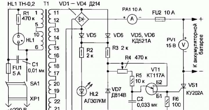
The figure shows a diagram of a thyristor charger, which automatically stops charging a car battery when the battery is fully charged.

Operating principle: the 220V mains voltage arriving at T1 is reduced and supplied to the rectifier diodes D1 D2, then the 12V voltage is supplied in two ways through D3R1R2 and the high power thyristor D4. Through the first circuit, the battery is charged with a current of only 0.1A. The value of this current is close to the self-discharge value of the battery, so even a long charge of the battery will not harm it and will always maintain it in full readiness. The current is set by resistor R2.
The second charging circuit goes through thyristor D4; a current of up to 6A can flow through it. The thyristor is controlled using a zener diode D6 (8V), a thyristor D7 and a voltage divider on R5R6, the middle point of which is connected through a diode D5 to the control electrode D4. The level of termination of charging with a large current is set using a voltage divider on R3 and variable R4. The constant voltage is removed from the R4 engine and controls the switching on and off of the thyristor D7 through the zener diode D6.
The threshold voltage at which the battery is fully charged and the charging current must be significantly reduced is set using resistor R4 individually for each battery.
When manufacturing a charger, a 100V transformer is required, the secondary winding of which must be designed for a voltage of 45V with a tap from the middle. If you don’t have the required transformer, you can take a power transformer from an old TV, leaving the primary winding unchanged, and wind the secondary winding at 45V. The number of turns should be as follows: the number of turns for heating the cathode of the kinescope multiplied by 7. The winding must be made of PEL, PEV-1, PEV-2 wire with a diameter of 2 mm.
Literature MRB 1018
- Similar articles
Login using:
Random articles
- 10.10.2014
The headphone amplifier can be directly connected to a CD player, tuner and tape recorder. Suitable for different headphone models - different impedance: 32, 100, 245, 300, 600 & 2000 Ohms. R3 is designed for headphone impedances up to 300 ohms. Over 600 ohm load or higher it is necessary to change R3 to 100K. Technical data: Consumed...
- 11.03.2015
The figure shows a diagram of a simple door open alarm. The circuit can be used to signal an open refrigerator door. The LED blinking frequency is 2Hz with a duty cycle of 10%. Current consumption during signaling is 60 mA. Since the door is closed most of the time, the battery charge will last for a long time. The input circuit is controlled by a 2N7000 N-channel MOSFET transistor when the reed switch closes the transistor...