Under normal operating conditions, the vehicle's electrical system is self-sufficient. We are talking about energy supply - a combination of a generator, a voltage regulator, and a battery works synchronously and ensures uninterrupted power supply to all systems.
This is in theory. In practice, car owners make amendments to this harmonious system. Or the equipment refuses to work in accordance with the established parameters.
For example:
- Operating a battery that has exhausted its service life. The battery does not hold a charge
- Irregular trips. Prolonged downtime of the car (especially during hibernation) leads to self-discharge of the battery
- The car is used for short trips, with frequent stopping and starting of the engine. The battery simply does not have time to recharge
- Connecting additional equipment increases the load on the battery. Often leads to increased self-discharge current when the engine is turned off
- Extremely low temperature accelerates self-discharge
- A faulty fuel system leads to increased load: the car does not start immediately, you have to turn the starter for a long time
- A faulty generator or voltage regulator prevents the battery from charging properly. This problem includes worn power wires and poor contact in the charging circuit.
- And finally, you forgot to turn off the headlights, lights or music in the car. To completely discharge the battery overnight in the garage, sometimes it is enough to close the door loosely. Interior lighting consumes quite a lot of energy.
Any of the following reasons leads to an unpleasant situation: you need to drive, but the battery is unable to crank the starter. The problem is solved by external recharge: that is, a charger.
The tab contains four proven and reliable car charger circuits from simple to the most complex. Choose any one and it will work.
A simple 12V charger circuit.
Charger with adjustable charging current.
Adjustment from 0 to 10A is carried out by changing the opening delay of the SCR. 
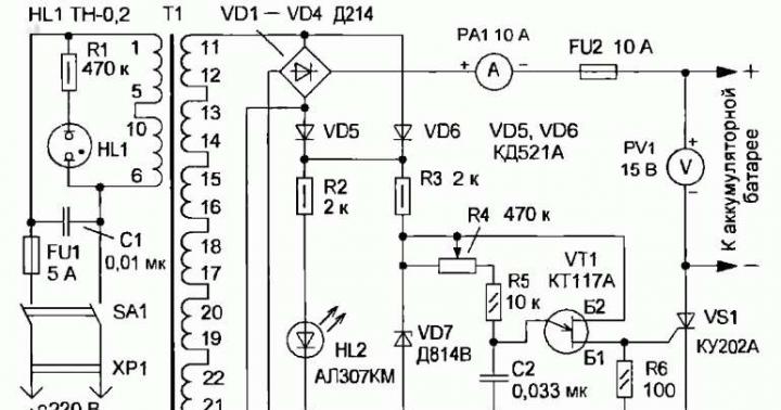
Circuit diagram of a battery charger with self-shutdown after charging.

For charging batteries with a capacity of 45 amps.
Scheme of a smart charger that will warn about incorrect connection. 
It is absolutely easy to assemble it with your own hands. An example of a charger made from an uninterruptible power supply.
Any car charger circuit consists of the following components:
- Power unit.
- Current stabilizer.
- Charge current regulator. Can be manual or automatic.
- Indicator of current level and (or) charge voltage.
- Optional - charge control with automatic shutdown.
Any charger, from the simplest to an intelligent machine, consists of the listed elements or a combination thereof.
Simple diagram for a car battery
Normal charge formula as simple as 5 kopecks - the basic battery capacity divided by 10. The charging voltage should be a little more than 14 volts (we are talking about a standard 12 volt starter battery).
I made this charger to charge car batteries, the output voltage is 14.5 volts, the maximum charge current is 6 A. But it can also charge other batteries, for example lithium-ion ones, since the output voltage and output current can be adjusted within a wide range. The main components of the charger were purchased on the AliExpress website.
These are the components:
You will also need an electrolytic capacitor 2200 uF at 50 V, a transformer for the TS-180-2 charger (see how to solder the TS-180-2 transformer), wires, a power plug, fuses, a radiator for the diode bridge, crocodiles. You can use another transformer with a power of at least 150 W (for a charging current of 6 A), the secondary winding must be designed for a current of 10 A and produce a voltage of 15 - 20 volts. The diode bridge can be assembled from individual diodes designed for a current of at least 10A, for example D242A.
The wires in the charger should be thick and short. The diode bridge must be fixed to a large radiator. It is necessary to increase the radiators of the DC-DC converter, or use a fan for cooling.


Charger Assembly
Connect a cord with a power plug and a fuse to the primary winding of the TS-180-2 transformer, install the diode bridge on the radiator, connect the diode bridge and the secondary winding of the transformer. Solder the capacitor to the positive and negative terminals of the diode bridge.

Connect the transformer to a 220 volt network and measure the voltages with a multimeter. I got the following results:
- The alternating voltage at the terminals of the secondary winding is 14.3 volts (mains voltage 228 volts).
- The constant voltage after the diode bridge and capacitor is 18.4 volts (no load).
Using the diagram as a guide, connect a step-down converter and a voltammeter to the DC-DC diode bridge.
Setting the output voltage and charging current
There are two trimming resistors installed on the DC-DC converter board, one allows you to set the maximum output voltage, the other allows you to set the maximum charging current.
Plug in the charger (nothing is connected to the output wires), the indicator will show the voltage at the device output and the current is zero. Use the voltage potentiometer to set the output to 5 volts. Close the output wires together, use the current potentiometer to set the short circuit current to 6 A. Then eliminate the short circuit by disconnecting the output wires and use the voltage potentiometer to set the output to 14.5 volts.
This charger is not afraid of a short circuit at the output, but if the polarity is reversed, it may fail. To protect against polarity reversal, a powerful Schottky diode can be installed in the gap of the positive wire going to the battery. Such diodes have a low voltage drop when connected directly. With such protection, if the polarity is reversed when connecting the battery, no current will flow. True, this diode will need to be installed on a radiator, since a large current will flow through it during charging.

Suitable diode assemblies are used in computer power supplies. This assembly contains two Schottky diodes with a common cathode; they will need to be paralleled. For our charger, diodes with a current of at least 15 A are suitable.

It must be taken into account that in such assemblies the cathode is connected to the housing, so these diodes must be installed on the radiator through an insulating gasket.
It is necessary to adjust the upper voltage limit again, taking into account the voltage drop across the protection diodes. To do this, use the voltage potentiometer on the DC-DC converter board to set 14.5 volts measured with a multimeter directly at the output terminals of the charger.
How to charge the battery
Wipe the battery with a cloth soaked in soda solution, then dry. Remove the plugs and check the electrolyte level; if necessary, add distilled water. The plugs must be turned out during charging. No debris or dirt should get inside the battery. The room in which the battery is charged must be well ventilated.
Connect the battery to the charger and plug the device into the mains. During charging, the voltage will gradually increase to 14.5 volts, the current will decrease over time. The battery can be conditionally considered charged when the charging current drops to 0.6 - 0.7 A.
Sometimes it happens that the battery in the car runs out and it is no longer possible to start it, since the starter does not have enough voltage and, accordingly, current to crank the engine shaft. In this case, you can “light it” from another car owner so that the engine starts and the battery starts charging from the generator, but this requires special wires and a person willing to help you. You can also charge the battery yourself using a specialized charger, but they are quite expensive and you don’t have to use them very often. Therefore, in this article we will take a detailed look at the homemade device, as well as instructions on how to make a charger for a car battery with your own hands.
Homemade device
Normal battery voltage when disconnected from the vehicle is between 12.5 V and 15 V. Therefore, the charger must output the same voltage. The charge current should be approximately 0.1 of the capacity, it can be less, but this will increase the charging time. For a standard battery with a capacity of 70-80 Ah, the current should be 5-10 amperes, depending on the specific battery. Our homemade battery charger must meet these parameters. To assemble a charger for a car battery, we need the following elements:
Transformer. Any old electrical appliance or one purchased on the market with an overall power of about 150 watts is suitable for us, more is possible, but not less, otherwise it will get very hot and may fail. It’s great if the voltage of its output windings is 12.5-15 V and the current is about 5-10 amperes. You can view these parameters in the documentation for your part. If the required secondary winding is not available, then it will be necessary to rewind the transformer to a different output voltage. For this:
Thus, we found or assembled the ideal transformer to make our own battery charger.
We will also need:

Having prepared all the materials, you can proceed to the process of assembling the car charger itself.
Assembly technology
To make a charger for a car battery with your own hands, you need to follow the step-by-step instructions:
- We create a homemade battery charging circuit. In our case it will look like this:

- We use transformer TS-180-2. It has several primary and secondary windings. To work with it, you need to connect two primary and two secondary windings in series to obtain the desired voltage and current at the output.

- Using a copper wire, we connect pins 9 and 9’ to each other.

- On a fiberglass plate we assemble a diode bridge from diodes and radiators (as shown in the photo).

- We connect pins 10 and 10’ to the diode bridge.
- We install a jumper between pins 1 and 1’.

- Using a soldering iron, attach a power cord with a plug to pins 2 and 2’.
- We connect a 0.5 A fuse to the primary circuit, and a 10-amp fuse to the secondary circuit, respectively.
- We connect an ammeter and a piece of nichrome wire into the gap between the diode bridge and the battery. One end of which is fixed, and the other must provide a moving contact, thus the resistance will change and the current supplied to the battery will be limited.
- We insulate all connections with heat shrink or electrical tape and place the device in the housing. This is necessary to avoid electric shock.
- We install a moving contact at the end of the wire so that its length and, accordingly, the resistance are maximum. And connect the battery. By decreasing or increasing the length of the wire, you need to set the desired current value for your battery (0.1 of its capacity).
- During the charging process, the current supplied to the battery will itself decrease and when it reaches 1 ampere, we can say that the battery is charged. It is also advisable to directly monitor the voltage on the battery, but to do this it must be disconnected from the charger, since when charging it will be slightly higher than the actual values.
The first start-up of the assembled circuit of any power source or charger is always carried out through an incandescent lamp if it lights up at full intensity - either there is an error somewhere, or the primary winding is short-circuited! An incandescent lamp is installed in the gap of the phase or neutral wire feeding the primary winding.
This circuit of a homemade battery charger has one big drawback - it does not know how to independently disconnect the battery from charging after reaching the required voltage. Therefore, you will have to constantly monitor the readings of the voltmeter and ammeter. There is a design that does not have this drawback, but its assembly will require additional parts and more effort.

A visual example of the finished product
Operating rules
The disadvantage of a homemade charger for a 12V battery is that after the battery is fully charged, the device does not automatically turn off. That is why you will have to periodically glance at the scoreboard in order to turn it off in time. Another important nuance is that checking the charger for spark is strictly prohibited.
Additional precautions to take include:
- when connecting the terminals, make sure not to confuse “+” and “-”, otherwise a simple homemade battery charger will fail;
- connection to the terminals should only be made in the off position;
- the multimeter must have a measurement scale greater than 10 A;
- When charging, you should unscrew the plugs on the battery to avoid its explosion due to boiling of the electrolyte.
Master class on creating a more complex model
That, in fact, is all I wanted to tell you about how to properly make a charger for a car battery with your own hands. We hope that the instructions were clear and useful for you, because... This option is one of the simplest types of homemade battery charging!
Also read:
We have repeatedly talked about all kinds of chargers for car batteries on a pulse basis, and today is no exception. And we will consider the design of an SMPS, which can have an output power of 350-600 watts, but this is not the limit, since the power, if desired, can be increased to 1300-1500 watts, therefore, on such a basis it is possible to build a starting-charger device, because at a voltage of 12 -14 Volts from a 1500 watt unit can draw up to 120 Amperes of current! well of course
The design attracted my attention a month ago, when an article caught my eye on one of the sites. The power regulator circuit seemed quite simple, so I decided to use this circuit for my design, which is very simple and does not require any adjustment. The circuit is designed for charging powerful acid batteries with a capacity of 40-100A/h, implemented on a pulse basis. The main power part of our charger is a mains switching power supply with power
Just recently I decided to make several chargers for car batteries, which I was going to sell on the local market. There were quite beautiful industrial buildings available; all you had to do was make a good filling and that was it. But then I encountered a number of problems, starting from the power supply and ending with the output voltage control unit. I went and bought a good old electronic transformer like Tashibra (Chinese brand) for 105 watts and started reworking it.
A fairly simple automatic charger can be implemented on the LM317 chip, which is a linear voltage regulator with an adjustable output voltage. The microcircuit can also work as a current stabilizer.
A high-quality charger for a car battery can be purchased on the market for $50, and today I will tell you the easiest way to make such a charger with minimal expenditure of money; it is simple and even a novice radio amateur can make it.
The design of a simple charger for car batteries can be implemented in half an hour at minimal cost; the process of assembling such a charger will be described below.
The article discusses a charger (charger) with a simple circuit design for batteries of various classes intended to power the electrical networks of cars, motorcycles, flashlights, etc. The charger is easy to use, does not require adjustments while charging the battery, is not afraid of short circuits, and is simple and cheap to manufacture.
Recently, I came across a diagram of a powerful charger for car batteries with a current of up to 20A on the Internet. In fact, this is a powerful regulated power supply assembled with just two transistors. The main advantage of the circuit is the minimum number of components used, but the components themselves are quite expensive, we are talking about transistors.
Naturally, everyone in the car has cigarette lighter chargers for all kinds of devices: navigator, phone, etc. The cigarette lighter is naturally not without dimensions, and especially since there is only one (or rather, a cigarette lighter socket), and if there is also a person who smokes, then the cigarette lighter itself must be taken out somewhere and put somewhere, and if you really need to connect something to the charger, then using the cigarette lighter for its intended purpose is simply impossible , you can solve the connection of all kinds of tees with a socket like a cigarette lighter, but it’s like that
Recently I came up with the idea of assembling a car charger based on cheap Chinese power supplies with a price of $5-10. In electronics stores you can now find units that are designed to power LED strips. Since such tapes are powered by 12 Volts, therefore the output voltage of the power supply is also within 12 Volts
I present the design of a simple DC-DC converter that will allow you to charge a mobile phone, tablet computer or any other portable device from a 12-volt car on-board network. The heart of the circuit is a specialized 34063api chip designed specifically for such purposes.
After the article charger from an electronic transformer, many letters were sent to my email address asking me to explain and tell how to power up the circuit of an electronic transformer, and in order not to write to each user separately, I decided to print this article, where I will talk about the main components that need will be modified to increase the output power of the electronic transformer.