Power supply repair
Among all the malfunctions, the repair of power supplies takes the first place. In the article "TV Power Supply Malfunctions" I described typical power supply failures. In this article, I want to describe the work and repair of power supplies in more detail.
You probably need to start with how to check after repair power supply so as not to cause it to break again. Although this method is considered controversial, I find it very effective.
So after repair the power supply you need to solder a 150-watt light bulb into the break of the fuse (it can be 100, but there may be a false glow), and solder a 40-60-watt light bulb into the break of the B + circuit (line power 95-145 volts, the track can simply be cut). Please note that some power supplies will not start at light load.
This system works like this. When plugged in after repair of the power supply, if it is working properly, the first light bulb at the moment of charging the network capacitor (100-220μF 450V) lights up and goes out as it charges. A weak glow remains. A 60-volt light bulb glows according to the voltage in the floor of the incandescence.
With a faulty power supply, a 150 W lamp glows with full incandescence. In some cases, this saves the transistor, microcircuit from repeated failure of key elements.
In the second method, the power transistor of the power supply is not soldered and the level and shape of the signal coming to it is analyzed using instruments (oscilloscope, multimeter).
Repair of the power supply unit.
In the description, I will rely on the diagram below.
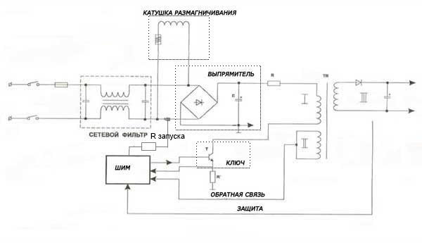
The mains fuse blows when the power is turned on.
Malfunctions can be caused by:
- demagnetization system;
- mains filter and rectifier;
- faulty key.
We check for a short circuit the elements of the mains filter, rectifier, thermistor - demagnetization system, the key and the elements of its strapping, as well as the key microcircuit (if the power supply is built on it).
When you find a faulty element, analyze the reasons for its failure. Failure of the transistor can be caused both by a voltage surge in the network, and by drying out of capacitors in the primary circuits.
The power supply does not turn on, the mains fuse is intact.
It should be checked for breakage: mains filter, rectifier, PWM - modulator.
Start by checking if the mains capacitor C has a constant voltage of about 300V (if not, look for a break in the mains filter, and also check the resistor R.
If there is + 300V on the capacitor C, check if it reaches the key transistor. You should also check the primary winding of the TP mains pulse transformer for breakage.
If all the elements are in good condition, and the power supply does not turn on, it is necessary to check the arrival of pulses to the base (gate) of the transistor.
Also check the trigger R circuitry, usually high resistance resistors.
Power supply protection is activated.
Check: the elements of the secondary rectifiers of the power supply, the loads of the power supply for a short circuit, the elements of the protection system (monitoring circuits for the output voltages), feedback circuits (modulator).
With the secondary circuits and their loads, I think everything is clear, it is necessary to check the rectifiers (diodes) and filter capacitors.
In the protection circuits, check the optocoupler and its piping.
With regards to the feedback circuits, check the zener diodes, diodes, capacitors (usually 4.7-10- 47 microfarads).
The voltages are overestimated or underestimated.
Check:
Network capacitor, capacitors of the PWM strapping, serviceability of the optocoupler and its strapping.
Malfunctions that appear periodically.
In this case, proceed as follows:
- check the soldering of the power supply elements for ring cracks;
- check the elements in the hottest places on the board by identifying them by blackening.
- In the event that a malfunction manifests itself when the TV is warming up, it is possible to localize the defective element either by cooling (cotton wool soaked in acetone, alcohol), or to speed up the occurrence of a malfunction by provoking it by heating one or another element with a soldering iron.
According to the statistics of service centers, the failure of power supplies is the most common cause of malfunctioning TVs. In modern TVs, switching power supplies of various designs and schematic constructions are used. However, most of their inherent malfunctions are similar, so the method of dealing with them can be used in various TV models.
Let's take a look at common device malfunctions associated with the operation of the power supply, their external manifestations, as well as ways to eliminate them.
The fuse blows when the TV is turned on.
This malfunction can be caused by the following reasons:
- Problems in the kinescope demagnetization system;
- Faults in the mains filter and rectifier;
- Failure of the transistor key.
- To find the cause of the problem, first of all we check if there are traces of a short circuit in the elements of the mains filter and rectifier of the power supply.
- Then we check the health of the thermistor (posistor), which is responsible for the correct operation of the screen demagnetization system.
- We make sure that the transistor switch and all the elements of its strapping are working correctly. If the power supply is built on a key microcircuit, then we check its serviceability.
At the same time, it is not enough to simply find the failed element. It is important to find the cause of the malfunction. For example, a malfunction of the key transistor can be triggered by a sharp voltage drop in the power supply network or by the failure (drying out) of the electrolytic capacitors of the primary circuits.
The power supply does not function, the mains fuse is OK
In this case, suspicion may fall on a power filter, rectifier elements and a PWM (pulse-width) modulator, which should be checked for breakage.
- Let's make sure that a constant voltage "hangs" on the network capacitor (about 300 V). If there is no voltage, then you should look for a break in the power filter or check the health of the resistor.
- We check if the voltage reaches the transistor switch. We make sure that there is no breakage in the primary winding of the pulse mains transformer.
- If no faults are found, we check whether pulses are supplied to the gate of the transistor, which works as a switch.
- It does not hurt to check the health of the starting circuit resistor, which usually has a high resistance rating.
The power supply protection system is activated
In this case, you should check the serviceability and absence of short circuits in the secondary rectifiers and power supply loads, as well as in the protection systems (output voltage level control circuits) and feedback (modulator).
In rectifiers, special attention should be paid to the serviceability of diodes and filter capacitors, and in the protection system, it is necessary to check the serviceability of the optocoupler and its accompanying elements (strapping).
In the feedback circuits, capacitors, zener diodes and diodes are subject to verification.
Power supply output voltages are abnormal
In this case, it is required to check the serviceability of the network capacitor, the elements for ensuring the operation of the PWM modulator and the protective optocoupler.
In case of periodic problems in the power supply
To find the causes of the malfunction, the following algorithm should be used:
- Carefully examine the soldering points of the power supply elements for the presence of circular cracks;
- Find elements with a blackened case in the power supply circuit, which indicates their overheating;
- If the malfunction begins to manifest itself only after the TV has warmed up, then the guilty element can be calculated by artificial cooling (wetting with alcohol or acetone) or heating (with a soldering iron). The nature of the behavior of the power supply unit in this case can significantly narrow the range of troubleshooting.
Malfunctions with TV power supplies
TV power supply
Despite the variety of schematic solutions, construction switching power supplies of modern TVs, many malfunctions of TV power supplies are typical for all power supplies.
The examples given are, of course, not complete when diagnosing power supply malfunctions, similar malfunctions can be caused by a change in the values of resistors in the primary circuits of the power supply unit, but these are more complex cases. It is better to start searching for such defects if the examples described below did not help.
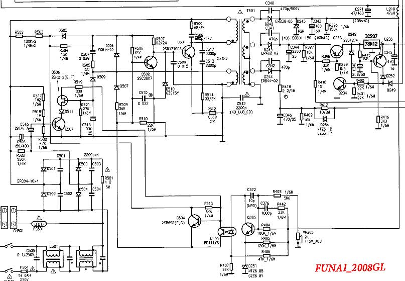
Let's look at a few TV power supply circuits built on transistors, a microcircuit (PWM controller) plus a power transistor and a power supply unit on one microcircuit (in a PWM case + a key transistor).
Transistor Power Supply, Funai 2008GL TV (1),
Rolsen C2131 power supply, PWM controller plus TV power transistor (2); 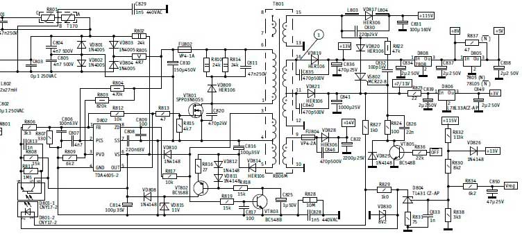
and (3) LG 20E60,21E60 power supply on chip (3). 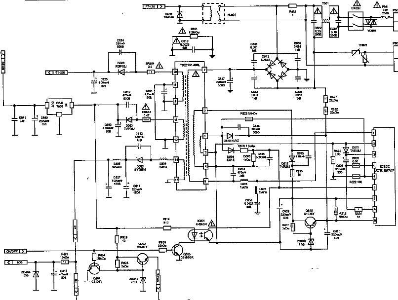
Typical malfunctions for all these PSUs are:
- Fuse is lit
- short circuit in the rectifier and load:
Funai - D501-D504, C506, Q501.
Rolsen - D801-D804, C810, VT801.
LG - D813, C817, IC802. - The power supply does not start, there is voltage on the rectifier, the key elements are in good order:
Funai - breakage R817, R818;
Rolsen - breakage R802;
LG - open circuit R827, R828. - Power supply unit does not start protection is triggered (ticks):
short circuit in secondary circuits, especially in V + power supply of the line operator (for different power supplies from 95 to 145 volts);
overestimated voltage V +. - The power supply goes into spacing, the key (power) transistor burns out:
capacitors in primary circuits;
optocoupler and optocoupler strapping. - The power (key) transistor burns out:
zener diodes and capacitors in primary circuits. - Understated voltage in secondary circuits:
rectifier line capacitor;
capacitors in the primary circuit.
It is no secret that a breakdown of a television receiver can ruin the mood of any owner. The question arises of where to look for a good master, whether it is necessary to take the device to service center? You need to spend your time on this, and what is important - money. But, before calling the master, if you have basic knowledge of electrical engineering and know how to hold a screwdriver and a soldering iron in your hands, then repairing the TV with your own hands in some cases is still possible.
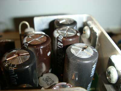
Modern LCD TVs have become more compact and easier to repair. Of course, there are breakdowns that are difficult to detect without special diagnostic equipment. But most often there are malfunctions that can be detected even visually, for example, swollen capacitors... With such a breakdown, it is enough to evaporate them and replace them with new ones with the same parameters.
All TV sets are the same in their device and consist of a power supply unit (PSU), a motherboard and an LCD backlight module (lamps are used) or LED (LEDs are used). It is not worth repairing the motherboard on your own, but the power supply unit and screen backlight lamps are quite possible.
Power supply repair
No TV signal
When repairing TVs LG, Sharp with LCD display, Rubin, Horizon with the same screens, a situation often arises when it does not turn on when the device is in good working order. It turns out that the cause may be in the antenna cable. This happens due to the operation of the noise reduction protection (in Rubin TVs, they began to install it not so long ago), and the unit goes into standby mode. Therefore, if you find your TV set in an inoperative state, you should not panic, but you need to check the presence of a signal from the transmitting station.
In conclusion, we can say - when you make a decision about self-repair TV receiver, you should soberly assess your abilities and knowledge in this matter. If you do not feel confident, then it is better to entrust this matter to a telemaster, especially since nobody canceled 220 V, and ignorance of basic safety rules can entail unpleasant consequences.
When diagnosing television devices, it takes incomparably more time to find a faulty component than to replace it, especially if the search for a defect is carried out on its own, and not by a professional TV technician. Of course, it is more logical to entrust the repair to a specialist who has experience and extensive practice of this kind of work, but if there is a desire, skills in handling a soldering iron and a tester, the necessary technical documentation in the form of a fundamental electrical circuit, you can try to fix the TV at home yourself.
The power supply unit of a modern TV, whether it is a plasma panel or LCD, LED TV, is a switching power supply with a given range of output supply voltages and rated power supplied to the load for each of them. The power board can be made as a separate unit, which is typical for receivers of small diagonals, or integrated into the television chassis and located inside the device.
The characteristic signs of a malfunction of this unit are as follows:
- The TV does not turn on when you press the power switch
- Standby LED is on, but no transition to operating mode
- Kinks and streaks in the picture, background sound
- There is sound, but there is no image, which may appear after a while
- It takes several attempts to turn on for a normal picture and sound to appear
Let's analyze the circuitry of a standard power supply and its typical malfunctions using the ViewSonic N3260W TV as an example.

To fully view the diagram, you can open it in a new window and enlarge it, or download it to your computer or mobile device.
The first thing to start with is a thorough visual inspection of the board with the device turned off from the network. To do this, the unit must be dismantled from the TV by disconnecting the connectors, and be sure to discharge the high-voltage capacitor in the filter - C1. In the blocks of this series of TVs, the electrolytic capacitors of the filters of the secondary power supplies often fail. They are easily diagnosed by a swollen top cover. All capacitors appearance which is in doubt, must be replaced immediately.
The standby node is made on IC2 (TEA1532A) and Q4 (04N70BF) with elements of stabilization of the output voltage 5V on the optocoupler IC7 and the controlled zener diode ICS3 EA1. Absent or underestimated voltage at the output of this node, measured on capacitors CS22, CS28, indicates its malfunction. The experience of restoring this section of the circuit shows that the most vulnerable elements are IC2, Q7, ZD4 and Q11, R64, R65, R67, which need to be checked and replaced if necessary. The performance of the parts is checked by a tester directly on the block board. In this case, dubious components are soldered and tested separately, in order to exclude the influence of neighboring circuit elements on their performance. IC2 simply needs to be replaced.
If there is a 5V voltage at the output of the standby circuit, a red LED lights up on the front of the TV. At a command from the remote control or a button on the front of the TV, the power supply should go into operating mode. This command - Power_ON - in the form of a high potential of about 5V comes to pin 1 of the CNS1 connector, opening the keys on QS4 and Q11. In this case, supply voltages are applied to the IC3 and IC1 microcircuits, transferring them to the operating mode. On the 8th pin of IC3 directly from the collector of Q11, on the 12th pin of IC1 through the switch Q9 after starting the PFC circuit. The performance of the Power Factor Correction circuit is indirectly determined by the voltage increase from 310 to 390 volts measured across C1. If there are output supply voltages 12V and 24V, then the main source on IC3, Q1, Q2 functions in normal mode. Practice shows the low reliability of the UCC28051 and LD6598D in critical conditions, when the filtration of secondary sources deteriorates, and their replacement is routine.
 Summarizing the experience of repairing television power supplies, it should be noted that the weakest link in their composition are filter capacitors, which lose their properties and nominal parameters over time. Sometimes the faulty "container" is visible by the swollen lid, sometimes not. The consequences of poor filtering of the rectified voltage can be very different: from the loss of the power supply itself, to damage to the elements of the inverter or a software failure on the memory chips on the motherboard.
It is very difficult to independently figure out all the causes and consequences when repairing a power supply unit of a modern TV, to diagnose it correctly without special tools and devices. Our advice in such cases is -