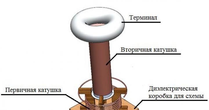
A transformer that increases voltage and frequency many times is called a Tesla transformer. Energy-saving and fluorescent lamps, picture tubes of old TVs, charging batteries from a distance and much more were created thanks to the operating principle of this device. Let’s not exclude its use for entertainment purposes, because the “Tesla transformer” is capable of creating beautiful purple discharges - streamers reminiscent of lightning (Fig. 1). During operation, an electromagnetic field is formed that can affect electronic devices and even the human body, and during discharges in the air a chemical process occurs with the release of ozone. To make a Tesla transformer with your own hands, you do not need to have extensive knowledge in the field of electronics, just follow this article.
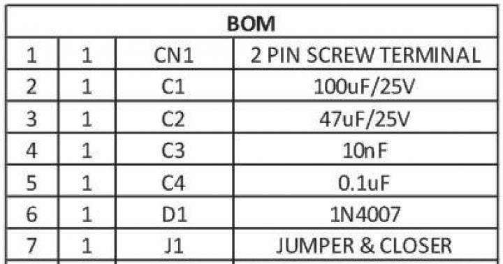
Components and operating principle
All Tesla transformers, due to a similar operating principle, consist of identical blocks:
- Power supply.
- Primary circuit.

The power supply provides the primary circuit with voltage of the required magnitude and type. The primary circuit creates high-frequency oscillations that generate resonant oscillations in the secondary circuit. As a result, a current of high voltage and frequency is formed on the secondary winding, which tends to create an electrical circuit through the air - a streamer is formed.
The choice of primary circuit determines the type of Tesla coil, power source and size of the streamer. Let's focus on the semiconductor type. It features a simple circuit with accessible parts and a low supply voltage.
Selection of materials and parts
We will search and select parts for each of the above structural units:


After winding, we insulate the secondary coil with paint, varnish or other dielectric. This will prevent the streamer from getting into it.
Terminal – additional capacity of the secondary circuit, connected in series. For small streamers it is not necessary. It is enough to bring the end of the coil up 0.5–5 cm.
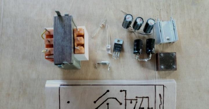
After we have collected all the necessary parts for the Tesla coil, we begin to assemble the structure with our own hands.
Design and assembly
We carry out the assembly according to the simplest scheme in Figure 4.

We install the power supply separately. The parts can be assembled by hanging installation, the main thing is to avoid short circuits between the contacts.
When connecting a transistor, it is important not to mix up the contacts (Fig. 5).

To do this, we check the diagram. We tightly screw the radiator to the transistor body.
Assemble the circuit on a dielectric substrate: a piece of plywood, a plastic tray, a wooden box, etc. Separate the circuit from the coils with a dielectric plate or board with a miniature hole for the wires.
We secure the primary winding so as to prevent it from falling and touching the secondary winding. In the center of the primary winding we leave space for the secondary coil, taking into account the fact that the optimal distance between them is 1 cm. It is not necessary to use a frame - a reliable fastening is enough.
We install and secure the secondary winding. We make the necessary connections according to the diagram. You can see the operation of the manufactured Tesla transformer in the video below.
Switching on, checking and adjusting
Before turning on, move electronic devices away from the test site to prevent damage. Remember electrical safety! To launch successfully, perform the following steps in order:
- We set the variable resistor to the middle position. When applying power, make sure there is no damage.
- Visually check the presence of the streamer. If it is missing, we bring a fluorescent light bulb or incandescent lamp to the secondary coil. The glow of the lamp confirms the functionality of the “Tesla transformer” and the presence of an electromagnetic field.
- If the device does not work, first of all we swap the leads of the primary coil, and only then we check the transistor for breakdown.
- When you turn it on for the first time, monitor the temperature of the transistor; if necessary, connect additional cooling.
Distinctive features of the powerful Tesla transformer are high voltage, large dimensions of the device and the method of producing resonant oscillations. Let's talk a little about how it works and how to make a Tesla spark-type transformer.
The primary circuit operates on alternating voltage. When turned on, the capacitor charges. As soon as the capacitor is charged to the maximum, a breakdown of the spark gap occurs - a device of two conductors with a spark gap filled with air or gas. After the breakdown, a series circuit of a capacitor and a primary coil is formed, called an LC circuit. It is this circuit that creates high-frequency oscillations, which create resonant oscillations and enormous voltage in the secondary circuit (Fig. 6).

If you have the necessary parts, you can assemble a powerful Tesla transformer with your own hands, even at home. To do this, it is enough to make changes to the low-power circuit:
- Increase the diameters of the coils and the cross-section of the wire by 1.1 - 2.5 times.
- Add a toroid-shaped terminal.
- Change the DC voltage source to an alternating one with a high boost factor that produces a voltage of 3–5 kV.
- Change the primary circuit according to the diagram in Figure 6.
- Add reliable grounding.
Tesla spark transformers can reach a power of up to 4.5 kW, therefore creating large-sized streamers. The best effect is obtained when the frequencies of both circuits are equal. This can be realized by calculating parts in special programs - vsTesla, inca and others. You can download one of the Russian-language programs from the link: http://ntesla.at.ua/_fr/1/6977608.zip.

Content:
A noticeable impetus in the development of electrical engineering occurred in the first years of the twentieth century, at which time society and industry evaluated innovative proposals from inventors. According to experts, many ideas can develop for several decades and even a hundred years. History keeps many secrets, including the innovative ideas and projects of Nikola Tesla - this name has become a mystery for many generations of people.
One of Tesla's famous inventions is the transformer he created, more often it is described as a Tesla coil (CT). A demonstration of its operation leaves no one indifferent; you can visually see electrical discharges that can have great significance. The simplicity of the design and the result obtained always make you want to make a similar coil yourself.
Tesla's resonant transformer, which in demonstration mode can show what manipulations with electricity and what techniques the inventor had at that time, has so far baffled traditional science.
The Nikola Tesla coil is a device that produces high-frequency currents. It is implemented using a primary and secondary winding, but the primary winding receives power at the resonance frequency of the secondary winding, and the output voltage increases tens of times.

Tesla patented this invention in 1896, which consists of the following elements:
- the primary winding is made of copper wire with a cross-section of at least 6 square millimeters, which is made in the form of 6–7 turns;
- the winding is secondary, it is implemented on a dielectric with a wire of 0.3 millimeters square and up to 800–1000 turns;
- discharge device;
- capacity (capacitor);
- spark radiation element.
The main difference between KT and all other transformers is that Nikola Tesla did not use ferrite alloys for the core in his invention, and the power of the resulting device depends only on the electrical permeability of air. The meaning of the idea is the creation of an oscillatory circuit, which can be done using several techniques:
- using frequency oscillations - this is a generator implemented on a discharge element;
- using lamps - an oscillation generator;
- using elements of radio engineering - transistors.
Purpose of the invention
According to experts, Tesla invented the transformer to solve the global issue of transmitting electrical energy from one point to another without the use of wires. In order to achieve the transmission of energy conceived by the inventor using the ether, it is necessary to have one powerful transformer at two remote points, which would operate at the same frequency in resonance.
If the project is implemented, then there will be no need for hydroelectric power stations, powerful power lines, or cable lines, which, of course, contradicts the monopoly ownership of electrical energy by different companies. With Nikola Tesla's project, every citizen of society could use electricity for free at the right time, anywhere, wherever he was. From a business point of view, this system is unprofitable, since it will not pay for itself, because electricity becomes free, which is why patent No. 645576 is still awaiting its investors.

How does a Tesla coil work?
To better understand the operation of a resonant transformer, experts recommend looking at its operation, since a simple coil circuit is intended to create a streamer. In other words, there is a loss of energy that goes to the capacitor if it is connected, but without it, a purple spark (streamer) flies out of the end of the high-voltage winding. A field appears around the emerging streamer, into which you can place a fluorescent lamp, and it will glow without being visually connected to any source of electrical energy.

When the capacitor is not used, the lamp glows brighter; some experts call Tesla's device a toy with exciting visual effects. There is always a desire to make such a device yourself; it implements various physical effects using two windings. An alternating voltage is applied to the primary winding, it creates a flux through which the energy is transferred to the secondary winding. Most transformers work on the same principle.
Main qualitative characteristics of CT:
- frequency in the secondary circuit;
- transmission coefficient of both windings;
- quality factor
Operating principle in simple words
The principle of operation of the Tesla coil is better understood if the entire operation of the device is compared with a swing - this is how we can approach the explanation of the accumulation of energy when a person, who is also the operator, appears to be the primary coil, and the movement of the swing is an electric current in winding No. 2. The lifting height is the potential difference.
In this example, the operator begins to swing the swing, in other words, transfer energy. In a couple of swings, the swing rises high, this corresponds to a large potential difference, a moment of excess energy comes, and as a result of this, a purple streamer appears.
The operator must swing the swing with a certain beat, which is set by the resonance frequency, in other words, the number of vibrations per second. The trajectory of the swing has a length - this is the coupling coefficient. When we swing the swing at arm's length and quickly, it is equal to one. A Tesla coil is the same transformer with an increased transmission coefficient.
When the operator swings the swing without holding it with his hand, this can be associated with small connections - the longer you swing, the further it goes. For rapid energy storage, the coupling coefficient must be large, but the potential difference at the output decreases.
The qualitative characteristic of the quality factor can be associated with the friction of a swing. The relationship is direct: with high friction, the quality factor is an insignificant value. The highest Q value will be at the highest point of the swing, when the highest value of the streamer appears.
Main types
Nikola Tesla's coil initially had one design - with a spark gap, but over time the element base expanded, many types of implementation of the great inventor's idea appeared, and all of them are called coils named after him. They are presented in abbreviation, in the English version.
The Tesla transformer circuit with arrester is a basic design that has negligible power if two wires are used. For higher power, a rotating spark gap for a powerful streamer is used.

The coil of a Tesla transformer implemented on a radio tube is a circuit that works without failures, showing powerful streamers that are used for high frequencies.

The coils are easy to control, but the principle of operation is the same as the Tesla transformer, implemented using transistors. There are many options for such reels:

Difficult to tune using semiconductor switches, two resonant coils with a short violet streamer length, compared to the spark gap, are characterized by poor controllability:

To improve the controllability of the CT, interrupters were made; with their help, the process was slowed down, and time appeared for charging capacitive storage devices (capacitors). This solution lengthens the discharge length.
Elements in different designs
To create a CT on their own, specialists have created a base of common elements that can be used in different implementations of a resonant transformer:
- A toroid having three main options:
- reduction of resonance;
- accumulation of charge magnitude: when the toroid is large, there is more energy;
- a field of static electricity is organized, which is repelled from the secondary winding. The option itself is implemented by the secondary winding, but the toroid helps it in this; the field repels the streamer and prevents it from hitting the second winding.
It is better to use a toroid in coils with a chopper, in which pumping occurs impulsively. It is recommended that the following condition be met: the value of the toroid diameter should be twice the value of the secondary winding diameter. The toroid is made from corrugation or similar materials.
Toroid in the diagram:

- The main component of the entire structure is the secondary coil (winding), it should be five times larger in diameter than the primary. The wire is taken with such a cross-section that at least 900–1000 turns, tightly wound and varnished, fit into the winding.
- The frame is made from PVC material, which is used in everyday life for plumbing fixtures.
- A protective ring, the functional purpose of which is to protect the primary winding from the streamer getting into it.
- The primary winding is usually made of a capacitor copper tube, the wire must have a large cross-section.
- The coupling coefficient affects the distance between the windings: the further away, the less coupling.
- Implementation of grounding, so that streamers hit it and close the current. If the grounding is poor, the streamer may hit the coil.
How to make a reel yourself
For home implementation of CT, any variant of elements can be used; you must remember the basic principle of its operation:
- it is necessary to make a primary and secondary winding;
- AC voltage is supplied to the primary winding;
- a magnetic field arises that will transfer electrical energy to the secondary winding;
- the secondary winding creates an oscillatory circuit, the task of which is to accumulate energy that will be stored by the circuit for some time.
- To wind the secondary winding you will need:
- two-inch pipe;
- wire 100 meters long, with enamel coating;
- two-inch PVC fitting;
- bolts and nuts, washers in assortment;
- copper tube 3 meters long.
- To make a capacitor yourself, you need the following parts:
- glass bottles, several pieces;
- rock salt;
- foil;
- special oil.
- The order of work is as follows:
- We wind the secondary winding; to do this, we fasten one end of the prepared wire in the upper part of a two-inch pipe, start winding, and do not allow the wire to intersect. The secondary winding is wound tightly. To fix the coil, we use masking tape, which is wound through 20 turns.
- We secure the resulting winding tightly with tape and cover the enamel with paint.
- To make winding easier, you can make a simple device to guide the wire through a wooden block:

- We make the primary winding. To wind it, we make a device from a metal flange installed in the center of the board and secured with bolts and nuts. We turn the copper pipe into a spiral, cutting it in such a way that when it is stretched, a cone is formed.
- We are making a spark gap, for this you will need two bolts and a wooden box.
- We make capacitors; to do this, we pour salted water into a prepared bottle, wrap the top with foil, and pass a metal wire through it into the bottle.
- We connect the wires as indicated in the diagram below, and be sure to ground them.
On the primary winding, 7 turns are obtained according to the scheme, on the secondary - 600.
Conclusion
Making a Tesla transformer with your own hands using electrical engineering skills is not so difficult, but it is recommended to make preliminary calculations, since the result may be a large device, and the sparks will significantly heat the space, as well as create the sound of a thunderclap. It is also necessary to take into account the influence of the created field on nearby electrical devices.
It is recommended to make a simple calculation of the arc, its length and power. To do this, take the distance between the electrodes (centimeters) and divide it by a factor of 4.25, then square the resulting value - this will be the arc power. We determine the distance as follows: take the resulting power and extract the square root from it, then multiply by a factor of 4.25. A discharge arc length of 150 centimeters will have a power of 1246 watts. A winding with a power of 1000 watts gives a discharge length of 137 centimeters.
You can make a generator that is powered by daylight. This is an excellent analogue of a solar panel, but the main advantage of such a generator is a minimum of materials, low cost and ease of assembly. Of course, such a generator will produce much less energy than a solar panel, but you can make a lot of them and thus get a good flow of free energy.
Nikola Tesla believed that the whole world is energy, so to receive and use it, you just need to assemble a device that could capture this free energy. He had many different projects for “fuel-free” generators. One of them, which today everyone can do with their own hands, will be discussed below.


The principle of operation of the device is that it uses the energy of the earth as a source of negative electrons, and the energy of the sun (or any other light source) as a source of positive electrons. As a result, a potential difference appears, which forms an electric current.
In total, the system has two electrodes, one is grounded, and the other is placed on the surface and captures energy sources (light sources). A large capacitor acts as a storage element. However, these days the capacitor can be replaced with a lithium-ion battery, connecting it through a diode so that the opposite effect does not occur.
Materials and tools for making a generator:
- foil;
- a sheet of cardboard or plywood;
- wires;
- high-capacity capacitor with high operating voltage (160-400 V);
- resistor (not required).

Manufacturing process:
Step one. Making grounding
First you need to make a good grounding. If the homemade product will be used in a country house or village, then you can drive a metal pin deeper into the ground, this will be grounding. You can also connect to existing metal structures that go into the ground.
If you use such a generator in an apartment, then water and gas pipes can be used as grounding. All modern sockets also have a ground connection; you can also connect to this contact.

Step two. Making a positive electron receiver
Now we need to make a receiver that could capture those free, positively charged particles that are produced along with the light source. Such a source can be not only the sun, but also already working lamps, various lamps, and the like. According to the author, the generator produces energy even in daylight in cloudy weather.
The receiver consists of a piece of foil, which is mounted on a sheet of plywood or cardboard. When light particles “bombard” an aluminum sheet, currents are formed in it. The larger the foil area, the more energy the generator will produce. To increase the power of the generator, several such receivers can be built and then all of them connected in parallel.

Step three. Connecting the circuit
At the next stage, you need to connect both contacts to each other, this is done through a capacitor. If you take an electrolytic capacitor, it is polar and has a designation on the body. The ground must be connected to the negative contact, and the wire going to the foil to the positive contact. Immediately after this, the capacitor will begin to charge and electricity can then be removed from it. If the generator turns out to be too powerful, the capacitor may explode from an excess of energy; therefore, a limiting resistor is included in the circuit. The more charged a capacitor is, the more it will resist further charging.
As for a conventional ceramic capacitor, their polarity does not matter.


Among other things, you can try to connect such a system not through a capacitor, but through a lithium battery, then it will be possible to accumulate much more energy.

That's all, the generator is ready. You can take a multimeter and check what voltage is already in the capacitor. If it is high enough, you can try connecting a small LED. Such a generator can be used for various projects, for example, for autonomous LED night lighting lamps.
In principle, instead of foil, you can use other materials, for example, copper or aluminum sheets. If someone in a private house has a roof made of aluminum (and there are many of them), then you can try to connect to it and see how much energy will be generated. It would also be a good idea to check whether such a generator can generate energy if the roof is metal. Unfortunately, no figures were presented that would show the current strength in relation to the area of the receiving contact.
The operation of CRT TVs, fluorescent and energy-saving light bulbs, and remote charging of batteries is provided by a special device - a Tesla transformer (coil). A Tesla coil is also used to create spectacular purple light charges reminiscent of lightning. The 220 V circuit allows you to understand the structure of this device and, if necessary, make it yourself.
Mechanism of operation
A Tesla coil is an electrical device capable of increasing voltage and current frequency several times. During its operation, a magnetic field is formed, which can affect electrical engineering and the human condition. Discharges entering the air contribute to the release of ozone. The transformer design consists of the following elements:
- Primary coil. It has an average of 5-7 turns of wire with a cross-sectional diameter of at least 6 mm².
- Secondary coil. Consists of 70−100 turns of dielectric with a diameter of no more than 0.3 mm.
- Capacitor.
- Discharger.
- Spark glow emitter.
![]() The transformer, created and patented by Nikola Tesla in 1896, does not have ferroalloys, which are used for cores in other similar devices. The power of the coil is limited by the electrical strength of the air and does not depend on the power of the voltage source.
The transformer, created and patented by Nikola Tesla in 1896, does not have ferroalloys, which are used for cores in other similar devices. The power of the coil is limited by the electrical strength of the air and does not depend on the power of the voltage source.
When voltage hits the primary circuit, high-frequency oscillations are generated on it. Thanks to them, resonant oscillations occur on the secondary coil, which results in an electric current characterized by high voltage and high frequency. The passage of this current through the air leads to the appearance streamer- a purple discharge resembling lightning.
Circuit oscillations that occur during the operation of a Tesla coil can be generated in different ways. Most often this happens using a spark gap, lamp or transistor. The most powerful devices are those that use double resonance generators.
Source materials
For a person with basic knowledge of physics and electrical engineering, it will not be difficult to assemble a Tesla transformer with your own hands. You just need to prepare a set of basic parts:

A mandatory element of the primary coil is a cooling radiator, the size of which directly affects the cooling efficiency of the equipment. A copper tube or wire with a diameter of 5-10 mm can be used as a winding.
The secondary coil requires mandatory insulation in the form of treatment with paint, varnish or other dielectric. An additional part of this circuit is a series-connected terminal. Its use is advisable only for powerful discharges; for small streamers, it is enough to move the end of the winding upward by 0.5-5 cm.
Connection diagram
The Tesla transformer is assembled and connected in accordance with the electrical diagram. Installation of a low-power device should be carried out in several stages:

The assembly of a more powerful transformer follows a similar scheme. To achieve high power, required:
The maximum power that a properly assembled Tesla transformer can achieve is up to 4.5 kW. This indicator can be achieved by equalizing the frequencies of both circuits.
A self-assembled Tesla coil must be checked. During test connection follows:
- Set the variable resistor to the middle position.
- Monitor the presence of a discharge. If it is absent, you need to bring a fluorescent lamp or incandescent lamp to the coil. Its glow will indicate the presence of an electromagnetic field and the operability of the transformer. Also, the serviceability of the device can be determined by self-igniting radio lamps and flashes at the end of the emitter.
The first start-up of the device should be carried out while monitoring the temperature. If the heat is very high, additional cooling must be connected.
Transformer Application
A coil can create different types of charges. Most often, during its operation, a charge appears in the form of an arc.
The glow of air ions in an electric field with increased voltage is called a corona discharge. It is a bluish radiation formed around coil parts that have significant surface curvature.
A spark discharge or spark passes from the transformer terminal to the surface of the earth or to a grounded object in the form of a beam of rapidly changing shape and fading bright stripes.
The streamer looks like a thin, weakly glowing light channel, which has many branches and consists of free electrons and ionized gas particles that do not go into the ground, but flow through the air.
The creation of various types of electrical discharges using a Tesla coil occurs with a large increase in current and energy, causing a crackling sound. The expansion of the channels of some discharges provokes an increase in pressure and the formation of a shock wave. The combination of shock waves sounds like the crackle of sparks when a flame burns.
Transformer effect this kind was previously used in medicine to treat diseases. High-frequency current flowing through human skin gave a healing and tonic effect. It turned out to be useful only under conditions of low power. When the power increased to high values, the opposite result was obtained, negatively affecting the body.
Using such an electrical device, gas-discharge lamps are ignited and leaks are detected in the vacuum space. It is also successfully used in the military sphere for the purpose of quickly destroying electrical equipment on ships, tanks or buildings. A powerful pulse generated by the coil in a very short period disables microcircuits, transistors and other devices located within a radius of tens of meters. The process of destroying equipment occurs silently.
The most spectacular area of application is demonstrative light shows. All effects are created due to the formation of powerful air charges, the length of which is measured in several meters. This property allows the transformer to be widely used when filming films and creating computer games.
When developing this device, Nikola Tesla planned to use it to transmit energy on a global scale. The scientist’s idea was based on the use of two strong transformers, located at different ends of the Earth and operating with an equal resonant frequency.
If such a power transmission system were successfully used, the need for power plants, copper cables and electricity suppliers would be completely eliminated. Every inhabitant of the planet would be able to use electricity anywhere absolutely free of charge. However, due to economic unprofitability, the famous physicist’s plan has not yet been (and is unlikely to ever be) realized.
In this article I will talk about the Tesla transformer device I assembled and the interesting effects that were observed in it during its operation.
I’d like to dot the i’s right away, this device works with high voltages, so compliance with basic safety rules is MANDATORY! Failure to follow the rules will result in serious injury, remember this! I would also like to note that the main danger in this device is the ISKROVIK (discharge arrester), which during its operation is a source of wide-spectrum radiation, including X-rays, remember this!
Let's begin. I’ll tell you briefly about the design of “my” Tesla transformer, in common parlance “Tesla coil”. This device is made on a simple element base, accessible to everyone. The block diagram of the device is shown below.
As you can see, I did not reinvent the wheel and decided to stick to the classic Tesla transformer circuit, the only thing added to the classic circuit is an electronic voltage converter - the role of which is to increase the voltage from 12 Volts to 10 thousand volts! By the way, this voltage converter can be assembled by a housewife. In the high-voltage part of the circuit, the following elements are used: The VD diode is a high-voltage 5GE200AF diode - it has high resistance - this is very important! Capacitors C1 and C2 have a nominal value of 2200 pF, each designed for a voltage of 5 kV. As a result, we get a total capacitance of 1100 pF and an accumulated voltage of 10 kV, which is very good for us! I would like to note that the capacitance is selected experimentally; the duration of the pulse in the primary coil depends on it, and of course on the coil itself. The pulse time must be less than the lifetime of electron pairs in the conductor of the primary coil of the Tesla transformer, otherwise we will have a low effect and the pulse energy will be spent on heating the coil - which we do not need! The assembled design of the device is shown below.
The design of the spark gap deserves special attention; most modern Tesla transformer circuits have a special spark generator design driven by an electric motor, where the discharge frequency is regulated by the rotation speed, but I decided not to follow this trend, since there are many negative aspects. I followed the classic arrester circuit. The technical drawing of the arrester is given below.
A cheap and practical option that does not make noise or light, I will explain why. This arrester is made of copper plates 2-3 mm thick with dimensions 30x30 mm (to act as a radiator, since the arc is a heat source) with threads for bolts in each plate. To prevent the bolt from unwinding during discharge and to ensure good contact, it is necessary to use a spring between the bolt and the plate. To dampen the noise during a discharge, we will make a special chamber where the arc will burn, my chamber is made from a piece of polyethylene water pipe (which does not contain reinforcement), the piece of pipe is clamped tightly between two plates and it is advisable to use sealing, for example, I have a special double-sided tape for insulation . The gap is adjusted by screwing in and unscrewing the bolt; I’ll explain why later.
Primary coil of the device. The primary coil of the device is made of copper wire type PV 2.5mm.kv and here the question arises: “Why such a thick wire?” I'll explain. The Tesla transformer is a special device, one might say anomalous, which is not of the same type as ordinary transformers, where the laws are completely different. For a conventional power transformer, self-induction (counter-EMF) is important in its operation, which compensates for part of the current; when a conventional power transformer is loaded, the counter-EMF decreases and the current increases accordingly; if we remove the counter-EMF from conventional transformers, they will flare up like candles. But in the Tesla transformer it’s the other way around - self-induction is our enemy! Therefore, to combat this disease, we use a thick wire that has low inductance, and therefore low self-inductance. We need a powerful electromagnetic pulse and we get it using this type of coil. The primary coil is made in the form of an Archimedes spiral in one plane in the amount of 6 turns, the maximum diameter of a large turn in my design is 60 mm.
The secondary coil of the device is a regular coil wound on a polymer water pipe (without reinforcement) with a diameter of 15 mm. The coil is wound with enamel wire 0.01mm.kv turn per turn, in my device the number of turns is 980 pcs. Winding the secondary coil requires patience and endurance, it took me about 4 hours.
So, the device is assembled! Now a little about adjusting the device, the device consists of two LC circuits - primary and secondary! For proper operation of the device, it is necessary to introduce the system into resonance, namely into resonance of the LC circuits. In fact, the system is brought into resonance automatically, due to the wide range of frequencies of the electric arc, some of which coincide with the impedance of the system, so all we have to do is optimize the arc and equalize the frequencies in terms of power in it - this is done very simply - we adjust the gap arrester. The arrester must be adjusted until the best results appear in the form of arc length. An image of the working device is located below.
So the device was assembled and launched - now it works for us! Now we can make our observations and study them. I want to immediately warn you: although high-frequency currents are harmless to the human body (in terms of the Tesla transformer), the light effects caused by them can affect the cornea of the eye and you risk getting a corneal burn, since the spectrum of the emitted light is shifted towards ultraviolet radiation. Another danger that lurks when using a Tesla transformer is an excess of ozone in the blood, which can lead to headaches, since large portions of this gas are produced during operation of the device, remember this!
Let's start observing a working Tesla coil. It is best to make observations in complete darkness, so you will most of all experience the beauty of all the effects that will simply amaze you with their unusualness and mystery. I made observations in complete darkness, at night and for hours I could admire the glow that the device produced, for which I paid the price the next morning: my eyes hurt like after a burn from electric welding, but these are trifles, as they say: “science requires sacrifices.” As soon as I turned on the device for the first time, I noticed a beautiful phenomenon - this is a glowing purple ball that was in the middle of the coil, in the process of adjusting the spark gap, I noticed that the ball moves up or down depending on the length of the gap, my only explanation for the phenomenon at the moment impedance in the secondary coil, which causes this effect. The ball consisted of many purple micro arcs that exited one area of the coil and entered another, forming a sphere. Since the secondary coil of the device is not grounded, an interesting effect was observed - purple glows at both ends of the coil. I decided to check how the device behaves with the secondary coil closed and noticed another interesting thing: an increase in the glow and an increase in the arc emanating from the coil when touching it - an amplification effect on the face. A repetition of Tesla's experiment, in which gas-discharge lamps glow in the field of a transformer. When a conventional energy-saving gas-discharge lamp is inserted into the transformer field, it begins to glow, the brightness of the glow is approximately 45% of its full power, which is approximately 8 W, while the power consumption of the entire system is 6 W. Just a note: a high-frequency electric field appears around the operating device, which has a potential of approximately 4 kV/cm2. An interesting effect is also observed: the so-called brush discharge, a luminous purple discharge in the form of a thick brush with frequent needles up to 20 mm in size, reminiscent of an animal’s fluffy tail. This effect is caused by high-frequency vibrations of gas molecules in the field of a conductor; in the process of high-frequency vibrations, gas molecules are destroyed and ozone is formed, and the residual energy manifests itself in the form of a glow in the ultraviolet range. The most striking manifestation of the brush effect occurs when using a flask with an inert gas, in my case I used a flask from a HPS gas discharge lamp, which contains Sodium (Na) in a gaseous state, and a bright brush effect occurs, which is similar to the burning of a wick only with very frequent formation of sparks, this effect is very beautiful.
Results of the work performed: The operation of the device is accompanied by various interesting and beautiful effects, which in turn deserve more careful study; it is known that the device generates a high frequency electric field, which causes the formation of a large amount of ozone, as a byproduct of ultraviolet glow. The special configuration of the device gives reason to think about the principles of its operation; there are only guesses and theories about the operation of this device, but no objective information has been put forward, just as there has been no thorough study of this device. At the moment, the Tesla transformer is collected by enthusiasts and used only for entertainment for the most part, although the device in my opinion is the key to understanding the fundamental basis of the universe that Tesla knew and understood. Using a Tesla transformer for fun is like hammering nails with a microscope... Super single effect of the device..? perhaps..., but I don’t yet have the necessary equipment to determine this fact.