If there is a need to regulate the speed of a motor connected to a 220 V network, we recommend assembling such a simple circuit. This motor rotation speed controller is distinguished by its low cost (the microcircuit on Aliexpress costs about 100 rubles), the presence of current feedback, and phase control of an AC electric motor.
AC Motor Regulator Diagram

The U2008B driver is designed for phase control and is made using bipolar technology. This allows you to control the current load level, as well as perform phase control compensation.
Specifications of AC Motor Speed Controller
- Power: 220V AC
- Load power: up to 500 W
- Soft start of the engine

The TIC226 triac requires a heat sink for higher loads. Up to 100 watts is not necessary. You can replace it with any other, for example the popular B138-600. If you notice, there is a jumper J1 installed on the printed circuit board: load current compensation or soft start. Trimmer resistor PR1 sets the range limits, and external variable P1 directly regulates the rotation speed of the connected motor.
Not every modern drill or grinder is equipped with a factory speed regulator, and most often speed control is not provided at all. However, both grinders and drills are built on the basis of commutator motors, which allows each of their owners, even if they know how to handle a soldering iron, to make their own speed controller from available electronic components, either domestic or imported.
In this article we will look at the diagram and principle of operation of the simplest engine speed controller for a power tool, and the only condition is that the engine must be a commutator type - with characteristic lamellas on the rotor and brushes (which sometimes spark).
The above diagram contains a minimum of parts and is suitable for power tools up to 1.8 kW and above, for a drill or grinder. A similar circuit is used to regulate speed in automatic washing machines that have commutator high-speed motors, as well as in dimmers for incandescent lamps. Such circuits, in principle, will allow you to regulate the heating temperature of a soldering iron tip, an electric heater based on heating elements, etc.
The following electronic components will be required:
Constant resistor R1 - 6.8 kOhm, 5 W.
Variable resistor R2 - 2.2 kOhm, 2 W.
Constant resistor R3 - 51 Ohm, 0.125 W.
Film capacitor C1 - 2 µF 400 V.
Film capacitor C2 - 0.047 uF 400 volts.
Diodes VD1 and VD2 - for voltage up to 400 V, for current up to 1 A.
Thyristor VT1 - for the required current, for a reverse voltage of at least 400 volts.
The circuit is based on a thyristor. A thyristor is a semiconductor element with three terminals: anode, cathode, and control electrode. After a short pulse of positive polarity is applied to the control electrode of the thyristor, the thyristor turns into a diode and begins to conduct current until this current in its circuit is interrupted or changes direction.
After the current stops or when its direction changes, the thyristor will close and stop conducting current until the next short pulse is applied to the control electrode. Well, since the voltage in the household network is alternating sinusoidal, then each period of the network sinusoid the thyristor (as part of this circuit) will work strictly starting from the set moment (in the set phase), and the less the thyristor is open during each period, the lower the speed will be power tool, and the longer the thyristor is open, the higher the speed will be.
As you can see, the principle is simple. But when applied to a power tool with a commutator motor, the circuit works more cleverly, and we will talk about this later.
So, the network here includes in parallel: a measuring control circuit and a power circuit. The measuring circuit consists of constant and variable resistors R1 and R2, capacitor C1, and diode VD1. What is this chain for? This is a voltage divider. The voltage from the divider, and what is important, the back-EMF from the motor rotor, add up in antiphase, and form a pulse to open the thyristor. When the load is constant, then the open time of the thyristor is constant, therefore the speed is stabilized and constant.
As soon as the load on the tool, and therefore on the engine, increases, the value of the back-EMF decreases, since the speed decreases, which means the signal to the control electrode of the thyristor increases, and opening occurs with less delay, that is, the power supplied to the engine increases, increasing the dropped speed . This way the speed remains constant even under load.

As a result of the combined action of signals from the back-EMF and from the resistive divider, the load does not greatly affect the speed, but without a regulator this influence would be significant. Thus, using this circuit, stable speed control is achievable in each positive half-cycle of the network sinusoid. At medium and low rotation speeds this effect is more pronounced.
However, with increasing speed, that is, with increasing voltage removed from the variable resistor R2, the stability of maintaining a constant speed decreases.
In this case, it is better to provide a shunt button SA1 parallel to the thyristor. The function of diodes VD1 and VD2 is to ensure half-wave operation of the regulator, since the voltages from the divider and the rotor are compared only in the absence of current through the motor.
Capacitor C1 expands the control zone at low speeds, and capacitor C2 reduces sensitivity to interference from brush sparking. The thyristor needs to be highly sensitive so that a current of less than 100 μA can open it.
When using an electric motor in tools, one of the serious problems is adjusting the speed of their rotation. If the speed is not high enough, then the tool is not effective enough.
If it is too high, then this leads not only to a significant waste of electrical energy, but also to possible burnout of the tool. If the rotation speed is too high, the operation of the tool may also become less predictable. How to fix it? For this purpose, it is customary to use a special rotation speed controller.
The motor for power tools and household appliances is usually one of 2 main types:
- Commutator motors.
- Asynchronous motors.
In the past, the second of these categories was most widespread. Nowadays, approximately 85% of motors used in electric tools, household or kitchen appliances are of the commutator type. This is explained by the fact that they are more compact, they are more powerful and the process of managing them is simpler.
The operation of any electric motor is based on a very simple principle: If you place a rectangular frame between the poles of a magnet, which can rotate around its axis, and pass a direct current through it, the frame will begin to rotate. The direction of rotation is determined according to the “right hand rule”.
This pattern can be used to operate a commutator motor.
The important point here is to connect the current to this frame. Since it rotates, special sliding contacts are used for this. After the frame rotates 180 degrees, the current through these contacts will flow in the opposite direction. Thus, the direction of rotation will remain the same. At the same time, smooth rotation will not work. To achieve this effect, it is customary to use several dozen frames.
Device

A commutator motor usually consists of a rotor (armature), stator, brushes and tachogenerator:
- Rotor- this is the rotating part, the stator is an external magnet.
- Brushes made of graphite- this is the main part of the sliding contacts, through which voltage is supplied to the rotating armature.
- Tachogenerator is a device that monitors rotation characteristics. In the event of a violation of the uniformity of movement, it adjusts the voltage supplied to the engine, thereby making it smoother.
- Stator may contain not one magnet, but, for example, 2 (2 pairs of poles). Also, instead of static magnets, electromagnet coils can be used here. Such a motor can operate on both direct and alternating current.
The ease of adjusting the speed of a commutator motor is determined by the fact that the rotation speed directly depends on the magnitude of the applied voltage.
In addition, an important feature is that the rotation axis can be directly attached to a rotating tool without the use of intermediate mechanisms.
If we talk about their classification, we can talk about:
- Brushed motors direct current.
- Brushed motors alternating current.
In this case, we are talking about what kind of current is used to power the electric motors.
Classification can also be made according to the principle of motor excitation. In a brushed motor design, electrical power is supplied to both the rotor and stator of the motor (if it uses electromagnets).
The difference lies in how these connections are organized.
Here it is customary to distinguish:
- Parallel excitation.
- Consistent excitation.
- Parallel-sequential excitation.
Adjustment
 Now let's talk about how you can regulate the speed of commutator motors. Due to the fact that the rotation speed of the motor simply depends on the amount of voltage supplied, any means of adjustment that are capable of performing this function are quite suitable for this.
Let's list a few of these options as examples:
- Laboratory autotransformer(LATR).
- Factory adjustment boards, used in household appliances (you can use in particular those used in mixers or vacuum cleaners).
- Buttons, used in the design of power tools.
- Household regulators lighting with smooth action.
However, all of the above methods have a very important flaw. Along with the decrease in speed, the engine power also decreases. In some cases, it can be stopped even just with your hand. In some cases, this may be acceptable, but in most cases, it is a serious obstacle.
A good option is to adjust the speed using a tachogenerator. It is usually installed at the factory. If there are deviations in the motor rotation speed, an already adjusted power supply corresponding to the required rotation speed is transmitted to the motor. If you integrate motor rotation control into this circuit, then there will be no loss of power.
How does this look constructively? The most common are rheostatic rotation control, and those made using semiconductors.
In the first case, we are talking about variable resistance with mechanical adjustment. It is connected in series to the commutator motor. The disadvantage is the additional heat generation and additional waste of battery life. With this adjustment method, there is a loss of engine rotation power. Is a cheap solution. Not applicable for sufficiently powerful motors for the reasons mentioned.
In the second case, when using semiconductors, the motor is controlled by applying certain pulses. The circuit can change the duration of such pulses, which in turn changes the rotation speed without loss of power.
How to make it yourself?
There are various options for adjustment schemes. Let us present one of them in more detail.
Here is how it works:

Initially, this device was developed to adjust the commutator motor in electric vehicles. We were talking about one where the supply voltage is 24 V, but this design is also applicable to other engines.
The weak point of the circuit, which was identified during testing of its operation, is its poor suitability at very high current values. This is due to some slowdown in the operation of the transistor elements of the circuit.
It is recommended that the current be no more than 70 A. There is no current or temperature protection in this circuit, so it is recommended to build in an ammeter and monitor the current visually. The switching frequency will be 5 kHz, it is determined by capacitor C2 with a capacity of 20 nf.
As the current changes, this frequency can change between 3 kHz and 5 kHz. Variable resistor R2 is used to regulate the current. When using an electric motor at home, it is recommended to use a standard type regulator.
At the same time, it is recommended to select the value of R1 in such a way as to correctly configure the operation of the regulator. From the output of the microcircuit, the control pulse goes to a push-pull amplifier using transistors KT815 and KT816, and then goes to the transistors.
The printed circuit board has a size of 50 by 50 mm and is made of single-sided fiberglass:

This diagram additionally shows 2 45 ohm resistors. This is done for the possible connection of a regular computer fan to cool the device. When using an electric motor as a load, it is necessary to block the circuit with a blocking (damper) diode, which in its characteristics corresponds to twice the load current and twice the supply voltage.
Operating the device in the absence of such a diode may lead to failure due to possible overheating. In this case, the diode will need to be placed on the heat sink. To do this, you can use a metal plate that has an area of 30 cm2.
Regulating switches work in such a way that the power losses on them are quite small. IN In the original design, a standard computer fan was used. To connect it, a limiting resistance of 100 Ohms and a supply voltage of 24 V were used.
The assembled device looks like this:


When manufacturing a power unit (in the lower figure), the wires must be connected in such a way that there is a minimum of bending of those conductors through which large currents pass. We see that the manufacture of such a device requires certain professional knowledge and skills. Perhaps in some cases it makes sense to use a purchased device.
Selection criteria and cost
In order to correctly choose the most suitable type of regulator, you need to have a good idea of what types of such devices there are:
- Various types of control. Can be a vector or scalar control system. The former are used more often, while the latter are considered more reliable.
- Regulator power must correspond to the maximum possible engine power.
- By voltage It is convenient to choose a device that has the most universal properties.
- Frequency characteristics. The regulator that suits you should match the highest frequency that the motor uses.
- Other characteristics. Here we are talking about the length of the warranty period, dimensions and other characteristics.
Depending on the purpose and consumer properties, prices for regulators can vary significantly.
For the most part, they range from approximately 3.5 thousand rubles to 9 thousand:
- Speed controller KA-18 ESC, designed for 1:10 scale models. Costs 6890 rubles.
- MEGA speed controller collector (moisture-proof). Costs 3605 rubles.
- Speed controller for LaTrax 1:18 models. Its price is 5690 rubles.
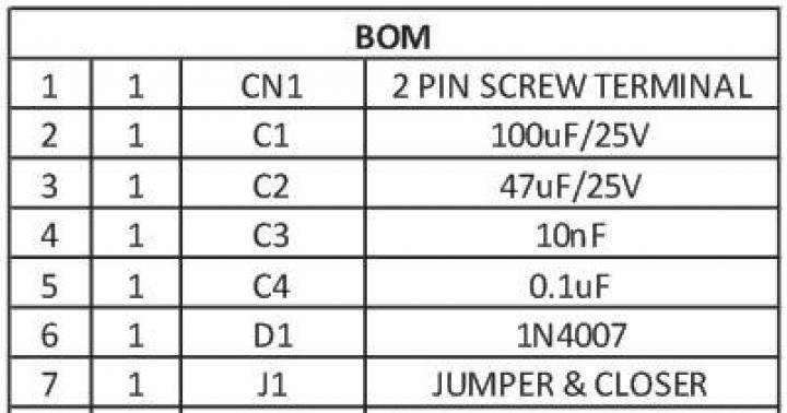
This DIY circuit can be used as a speed controller for a 12V DC motor with a current rating of up to 5A, or as a dimmer for 12V halogen and LED lamps up to 50W. Control is carried out using pulse width modulation (PWM) at a pulse repetition rate of about 200 Hz. Naturally, the frequency can be changed if necessary, selecting for maximum stability and efficiency.
Most of these structures are assembled at a much higher cost. Here we present a more advanced version that uses a 7555 timer, a bipolar transistor driver and a powerful MOSFET. This design provides improved speed control and operates over a wide load range. This is indeed a very effective scheme and the cost of its parts when purchased for self-assembly is quite low.
The circuit uses a 7555 Timer to create a variable pulse width of about 200 Hz. It controls transistor Q3 (via transistors Q1 - Q2), which controls the speed of the electric motor or light bulbs.
![]()
![]()
There are many applications for this circuit that will be powered by 12V: electric motors, fans or lamps. It can be used in cars, boats and electric vehicles, in model railways and so on.
![]()
12 V LED lamps, for example LED strips, can also be safely connected here. Everyone knows that LED bulbs are much more efficient than halogen or incandescent bulbs and will last much longer. And if necessary, power the PWM controller from 24 volts or more, since the microcircuit itself with a buffer stage has a power stabilizer.
Each of us has some kind of electrical appliance at home that has been working in the house for more than one year. But over time, the power of the technology weakens and does not fulfill its intended purpose. This is when you should pay attention to the insides of the equipment. Mostly problems arise with the electric motor, which is responsible for the functionality of the equipment. Then you should turn your attention to a device that regulates engine speed without reducing its power.
Types of engines
 A speed control with power maintenance is an invention that will breathe new life into an electrical appliance, and it will work like a newly purchased product. But it is worth remembering that engines come in different formats and each has its own maximum performance.
The engines have different characteristics. This means that this or that technique operates at different speeds of the shaft that triggers the mechanism. The motor may be:
- single-phase,
- two-phase,
- three-phase.
Mostly three-phase electric motors are found in factories or large factories. At home, single-phase and two-phase are used. This electricity is enough to operate household appliances.
Power speed regulator
Work principles
 A 220 V electric motor speed controller without loss of power is used to maintain the initial set shaft speed. This is one of the basic principles of this device, which is called a frequency regulator.
With its help, the electrical device operates at the set engine speed and does not reduce it. The engine speed controller also affects the cooling and ventilation of the motor. With the help of power, the speed is set, which can be either raised or reduced.
Many people have asked the question of how to reduce the speed of a 220 V electric motor. But this procedure is quite simple. One has only to change the frequency of the supply voltage, which will significantly reduce the performance of the motor shaft. You can also change the power supply to the motor by activating its coils. Electrical control is closely related to the magnetic field and motor slip. For such actions, they mainly use an autotransformer and household regulators, which reduce the speed of this mechanism. But it is also worth remembering that engine power will decrease.
Shaft rotation
Engines are divided into:
- asynchronous,
- collector
The speed controller of an asynchronous electric motor depends on the current connection to the mechanism. The essence of the operation of an asynchronous motor depends on the magnetic coils through which the frame passes. It rotates on sliding contacts. And when, when turning, it turns 180 degrees, then through these contacts the connection will flow in the opposite direction. This way the rotation will remain the same. But with this action the desired effect will not be obtained. It will come into force after a couple of dozen frames of this type are added to the mechanism.
 The commutator motor is used very often. Its operation is simple, since the passed current passes directly - because of this, the power of the electric motor is not lost, and the mechanism consumes less electricity.
The washing machine motor also needs power adjustment. For this purpose, special boards were made that cope with their job: the engine speed control board from a washing machine has multifunctional use, since its use reduces the voltage, but does not lose rotation power.
The circuit of this board has been verified. All you have to do is install diode bridges and select an optocoupler for the LED. In this case, you still need to put a triac on the radiator. Basically, engine adjustment starts at 1000 rpm.
If you are not satisfied with the power regulator and its functionality is lacking, you can make or improve the mechanism. To do this, you need to take into account the current strength, which should not exceed 70 A, and heat transfer during use. Therefore, an ammeter can be installed to adjust the circuit. The frequency will be small and will be determined by capacitor C2.
Next, you should configure the regulator and its frequency. When outputting, this pulse will go out through a push-pull amplifier using transistors. You can also make 2 resistors that will serve as an output for the computer's cooling system. To prevent the circuit from burning out, a special blocker is required, which will serve as double the current value. So this mechanism will work for a long time and in the required volume. Power regulating devices will provide your electrical appliances with many years of service without special costs.