Voltage measurements in practice have to be performed quite often. Voltage is measured in radio engineering, electrical devices and circuits, etc. The type of alternating current can be pulsed or sinusoidal. Voltage sources are either current generators.
Types of voltage measurement
The pulse current voltage has the parameters of the amplitude and average voltage. Pulse generators can be sources of such voltage. Voltage is measured in volts and is designated "V" or "V". If the voltage is variable, then the symbol “ ~ ”, for constant voltage, the symbol “-” is indicated. The alternating voltage in the home household network is marked ~ 220 V.

These are devices designed to measure and control the characteristics of electrical signals. Oscilloscopes work on the principle of deflecting an electron beam, which produces an image of the values of variables on the display.
AC voltage measurement
According to regulatory documents, the voltage in the household network should be equal to 220 volts with a deviation accuracy of 10%, that is, the voltage can vary in the range of 198-242 volts. If the lighting in your house has become dimmer, the lamps began to fail frequently, or household devices began to work unstable, then to find out and fix these problems, you first need to measure the voltage in the network.
Before measurement, prepare the existing measuring device for operation:
- Check the integrity of the insulation of the control wires with probes and tips.
- Set the switch to AC voltage, with an upper limit of 250 volts or higher.
- Insert the tips of the control wires into the sockets of the measuring device, for example, . In order not to be mistaken, it is better to look at the designations of the sockets on the case.
- Turn on the device.
The measurement limit of 700 volts is selected on the multimeter. Some devices require several different switches to be set to the desired position to measure voltage: the type of current, the type of measurement, and also insert the wire lugs into certain sockets. The end of the black tip in the multimeter is plugged into the COM jack (common jack), the red tip is inserted into the socket marked “V”. This socket is common for measuring any kind of voltage. The socket marked "ma" is used for measuring small currents. The socket marked "10 A" is used to measure a significant amount of current, which can reach 10 amperes.
If you measure the voltage with the wire inserted into the “10 A” socket, the device will fail or the fuse will blow. Therefore, when performing measurement work, you should be careful. Most often, errors occur in cases where the resistance was first measured, and then, forgetting to switch to another mode, the voltage measurement begins. At the same time, a resistor responsible for measuring resistance burns inside the device.
After preparing the device, you can start measuring. If nothing appears on the indicator when you turn on the multimeter, this means that the battery located inside the device has expired and needs to be replaced. Most often in multimeters there is a "Krona", which produces a voltage of 9 volts. Its service life is about a year, depending on the manufacturer. If the multimeter has not been used for a long time, then the crown may still be faulty. If the battery is good, then the multimeter should show one.
The wire probes must be inserted into the socket or touched with bare wires.

On the display of the multimeter, the value of the mains voltage will immediately appear in digital form. On the pointer device, the arrow will deviate by a certain angle. The pointer tester has several graduated scales. If you carefully consider them, then everything becomes clear. Each scale is designed for specific measurements: current, voltage or resistance.
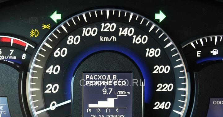
The measurement limit on the device was set to 300 volts, so you need to count on the second scale, which has a limit of 3, while the readings of the device must be multiplied by 100. The scale has a division value of 0.1 volts, so we get the result shown in the figure, about 235 volts. This result is within acceptable limits. If the measurement constantly changes during measurement, there may be poor contact in the electrical wiring connections, which can lead to sparking and malfunctions in the network.
DC voltage measurement
Sources of constant voltage are batteries, low-voltage or batteries, the voltage of which is not more than 24 volts. Therefore, touching the poles of the battery is not dangerous, and there is no need for special safety measures.
To assess the performance of a battery or other source, it is necessary to measure the voltage at its poles. For finger batteries, the power poles are located at the ends of the case. The positive pole is marked "+".

Direct current is measured in the same way as alternating current. The difference lies only in setting the device to the appropriate mode and observing the polarity of the outputs.
The battery voltage is usually marked on the case. But the result of the measurement does not yet indicate the health of the battery, since the electromotive force of the battery is measured in this case. The duration of operation of the device in which the battery will be installed depends on its capacity.
To accurately assess the performance of the battery, it is necessary to measure the voltage with the load connected. For a finger battery, a regular 1.5 volt flashlight bulb is suitable as a load. If the voltage drops slightly when the light is on, that is, no more than 15%, then the battery is suitable for use. If the voltage drops much more, then such a battery can still serve only in a wall clock, which consumes very little energy.
Voltmeter is a measuring device that is designed to measure voltage direct or alternating current in electrical circuits.
The voltmeter is connected in parallel to the outputs of the voltage source using remote probes. According to the method of displaying the results of measurements, voltmeters are pointer and digital.
The voltage value is measured in volts, is indicated on the instruments by the letter IN(in Russian) or Latin letter V(international designation).

On electrical circuits, the voltmeter is indicated by the Latin letter V, circled, as shown in the photo.
The voltage is either constant or variable. If the voltage of the current source is alternating, then the sign " is placed in front of the value ~ "if constant, then sign" – ".
For example, the alternating voltage of a household network of 220 Volts is briefly indicated as follows: ~220 V or ~220 V. On batteries and accumulators, when they are marked, the sign " – "often omitted, just a number. The voltage of the on-board network of a car or battery is indicated as follows: 12 V or 12V, and batteries for a flashlight or camera: 1.5V or 1.5V. It is mandatory to mark the body near the positive terminal in the form of the sign " + ".
The polarity of an alternating voltage changes with time. For example, the voltage in a household electrical wiring changes polarity 50 times per second (the frequency of the change is measured in Hertz, one Hertz is equal to one change in the polarity of the voltage in one second).
The polarity of the DC voltage does not change over time. Therefore, different measuring instruments are required to measure AC and DC voltage.
There are universal voltmeters with which you can measure both AC and DC voltage without switching operating modes, for example, a voltmeter type E533.
How to measure the voltage in the electrical wiring of a household network
Attention! When measuring voltages above 36 V, it is unacceptable to touch bare wires, as this can lead to electric shock!
According to the requirements of GOST 13109-97, the effective value of the voltage in the electrical network must be 220V±10%, that is, it can vary from 198V to 242V. If the light bulbs began to dimly burn in the apartment or often burn out, household appliances became unstable, then in order to take action, you must first measure the voltage value in the electrical wiring.
When starting measurements, it is necessary to prepare the device: - check the reliability of the insulation of conductors with lugs and probes; - set the switch of measurement limits to the position of measuring alternating voltage of at least 250 V; 
- insert the connectors of the conductors into the sockets of the device, guided by the inscriptions near them;

– turn on the measuring device (if necessary).
As you can see in the picture, the AC voltage measurement limit of 300 V is selected in the tester, and 700 V in the multimeter. In many models of testers, you need to set several switches to the required position at once. The type of current (~ or -), the type of measurement (V, A or Ohm) and also insert the ends of the probes into the desired sockets.
In the multimeter, the end of the black probe is inserted into the COM jack (common for all measurements), and the red one into V, common for changing DC and AC voltage, current, resistance and frequency. The jack marked ma is used to measure low currents, 10 A while measuring currents as high as 10 A.
Attention! Measuring voltage while the plug is plugged into the 10A socket will damage the instrument. In the best case, the fuse inserted inside the device will blow, in the worst case, you will have to buy a new multimeter. Especially often they make mistakes when using instruments for measuring resistance, and, forgetting to switch the mode, they measure the voltage. I met more than a dozen of such faulty devices, with burnt resistors inside.
After carrying out all the preparatory work, you can start measuring. If you turned on the multimeter, and no numbers appeared on the indicator, it means that either the battery is not installed in the device or it has already exhausted its resource. Typically, multimeters use a Krona-type battery with a voltage of 9 V, the shelf life of which is one year. Therefore, even if the device has not been used for a long time, the battery may not work. When using the multimeter in stationary conditions, it is advisable to use an adapter ~ 220 V / -9 V instead of a crown.
Insert the ends of the probes into the outlet or touch them to the wires of the electrical wiring.

The multimeter will immediately show the voltage in the network, but in the switch tester, the readings must also be able to read. At first glance, it seems that it is difficult, since there are many scales. But if you look closely, it becomes clear on what scale to read the readings of the device. On the considered device of the TL-4 type (which has served me flawlessly for more than 40 years!) There are 5 scales.
The upper scale is used to take readings when the switch is in multiples of 1 (0.1, 1, 10, 100, 1000). The scale, located just below, is a multiple of 3 (0.3, 3, 30, 300). When measuring AC voltage of 1 V and 3 V, 2 more additional scales are applied. There is a separate scale for measuring resistance. All testers have a similar graduation, but the multiplicity can be any.
Since the measurement limit was set to ~ 300 V, it means that the reading must be made on the second scale with a limit of 3, multiplying the readings by 100. The price of a small division is 0.1, therefore, it turns out 2.3 + the arrow is in the middle between the strokes, which means we take the value of the readings 2.35 × 100 \u003d 235 V.
It turned out that the measured voltage value is 235 V, which is within the permissible range. If during the measurement process there is a constant change in the value of the low-order digits, and the arrow on the tester constantly fluctuates, then there are bad contacts in the wiring connections and it is necessary to revise it.
How to measure battery voltage
battery or power supply
Since the voltage of direct current sources usually does not exceed 24 V, touching the terminals and bare wires is not dangerous for humans and special safety measures are not required.
In order to assess the suitability of a battery, accumulator or the health of a power supply, it is required to measure the voltage at their terminals. The terminals of round batteries are located at the ends of the cylindrical body, the positive terminal is indicated by the “+” sign.

Measuring DC voltage is practically not much different from measuring AC voltage. You just need to switch the device to the appropriate measurement mode and observe the polarity of the connection.

The amount of voltage that a battery creates is usually marked on its case. But even if the measurement result showed sufficient voltage, this does not mean that the battery is good, since the EMF (electromotive force) was measured, and not the capacity of the battery, which determines the duration of the product in which it will be installed.

For a more accurate assessment of the battery capacity, you need to measure the voltage by connecting a load to its poles. An incandescent lamp for a flashlight, designed for a voltage of 1.5 V, is well suited as a load for a 1.5 V battery. For convenience, you need to solder conductors to its base.
If the voltage under load decreases by less than 15%, then the battery or accumulator is quite suitable for operation. If there is no measuring device, then you can judge the suitability for further use of the battery by the brightness of the light bulb. But such a check cannot guarantee the duration of the battery in the device. It only indicates that the battery is currently still usable.
The basic unit of measurement for electrical voltage is the volt. Depending on the magnitude, the voltage can be measured in volts(IN), kilovolts(1 kV = 1000 V), millivolts(1 mV = 0.001 V), microvolts(1 uV = 0.001mV = 0.000001 V). In practice, most often, one has to deal with volts and millivolts.
There are two main types of voltages - permanent And variable. Batteries are the source of constant voltage. The source of alternating voltage can be, for example, the voltage in the electrical network of an apartment or house.
Used to measure voltage voltmeter. Voltmeters are turnouts(analog) and digital.
To date, pointer voltmeters are inferior to digital ones, since the latter are more convenient to use. If, when measuring with a pointer voltmeter, the voltage readings have to be calculated on a scale, then for a digital one, the measurement result is immediately displayed on the indicator. And in terms of dimensions, the pointer device loses to the digital one.
But this does not mean that pointer devices are not used at all. There are some processes that cannot be seen with a digital device, so turnouts are more used in industrial enterprises, laboratories, repair shops, etc.
On electrical circuit diagrams, a voltmeter is indicated by a circle with a capital Latin letter " V" inside. Next to the symbol of the voltmeter, its letter designation " PU” and the serial number in the scheme. For example. If there are two voltmeters in the circuit, then near the first they write " PU 1", and about the second " PU 2».
When measuring direct voltage, the diagram indicates the polarity of the voltmeter connection, but if alternating voltage is measured, then the polarity of the connection is not indicated.

Voltage is measured between two points circuits: in electronic circuits between positive And negative poles, in electrical circuits between phase And zero. Voltmeter connected parallel to voltage source or parallel to the chain- a resistor, lamp or other load on which it is necessary to measure the voltage:

Consider connecting a voltmeter: in the upper circuit, the voltage is measured on a lamp HL1 and at the same time on the power supply GB1. In the diagram below, the voltage is measured across the lamp. HL1 and resistor R1.
Before measuring the voltage, determine it view and approximate value. The fact is that for voltmeters, the measuring part is designed for only one type of voltage, and this results in different measurement results. A voltmeter for measuring direct voltage does not see an alternating voltage, and a voltmeter for alternating voltage, on the contrary, can measure a direct voltage, but its readings will not be accurate.
Knowing the approximate value of the measured voltage is also necessary, since voltmeters operate in a strictly defined voltage range, and if you make a mistake with the choice of range or value, the device can be damaged. For example. The measurement range of the voltmeter is 0 ... 100 Volts, which means that the voltage can only be measured within these limits, since when measuring voltage above 100 Volts, the device will fail.
In addition to devices that measure only one parameter (voltage, current, resistance, capacitance, frequency), there are multifunctional devices that measure all these parameters in one device. Such a device is called tester(mostly pointer gauges) or digital multimeter.

We will not dwell on the tester, this is the topic of another article, but we will immediately move on to a digital multimeter. For the most part, multimeters can measure two types of voltage in the range of 0 ... 1000 Volts. For ease of measurement, both voltages are divided into two sectors, and in sectors into sub-ranges: the constant voltage has five sub-ranges, the alternating voltage has two.

Each subrange has its own maximum measurement limit, which is indicated by a numerical value: 200m, 2V, 20V, 200V, 600V. For example. At the "200V" limit, the voltage is measured in the range of 0 ... 200 Volts.
Now the process of measurement.
1. DC voltage measurement.
First, we define view measured voltage (DC or AC) and move the switch to the desired sector. For example, let's take a finger-type battery, the constant voltage of which is 1.5 Volts. We select the constant voltage sector, and in it the measurement limit is “2V”, the measurement range of which is 0 ... 2 Volts.
The test leads must be inserted into the sockets as shown in the figure below:
red the probe is called positive, and it is inserted into the socket opposite which the icons of the measured parameters are shown: "VΩmA";
black dipstick is called negative or general and it is inserted into the socket, opposite which is the "COM" icon. All measurements are made relative to this probe.

With the positive probe we touch the positive pole of the battery, and with the negative one - the negative one. The measurement result of 1.59 Volts is immediately visible on the multimeter indicator. As you can see, everything is very simple.


Now another nuance. If the probes on the battery are interchanged, then a minus sign will appear in front of the unit, indicating that the polarity of the multimeter connection is reversed. The minus sign can be very convenient in the process of setting up electronic circuits, when you need to determine the positive or negative tires on the board.

Well, now consider the option when the magnitude of the voltage is unknown. Let's leave a finger battery as a voltage source.
Suppose we do not know the battery voltage, and in order not to burn the device, we start the measurement from the maximum limit of “600V”, which corresponds to the measurement range of 0 ... 600 Volts. With the probes of the multimeter, we touch the poles of the battery and on the indicator we see the measurement result equal to " 001 ". These figures indicate that there is no voltage or its value is too small, or the measurement range is too large.

We go down below. We switch the switch to the “200V” position, which corresponds to the range of 0 ... 200 Volts, and touch the battery poles with the probes. The indicator showed readings equal to " 01,5 ". In principle, these readings are already enough to say that the voltage of the AA battery is 1.5 volts.

However, the zero in front suggests dropping even lower and more accurately measuring the voltage. We decrease to the limit of "20V", which corresponds to the range of 0 ... 20 Volts, and again we measure. The display shows " 1,58 ". Now we can say with accuracy that the voltage of a finger battery is 1.58 volts.

In this way, not knowing the magnitude of the voltage, they find it, gradually decreasing from a high measurement limit to a low one.
There are also situations when, when measuring, the unit “ 1 ". The unit signals that the measured voltage or current is above the selected measurement limit. For example. If you measure a voltage of 3 Volts at the “2V” limit, then a unit will appear on the indicator, since the measurement range of this limit is only 0 ... 2 Volts.

There is one more limit "200m" with a measurement range of 0 ... 200 mV. This limit is designed to measure very small voltages (millivolts), which are sometimes encountered when setting up some kind of amateur radio design.

2. AC voltage measurement.
The process of measuring AC voltage is no different from measuring DC voltage. The only difference is that for alternating voltage, the polarity of the probes is not required.
The AC voltage sector is divided into two subranges 200V And 600V.
At the "200V" limit, you can measure, for example, the output voltage of the secondary windings of step-down transformers, or any other voltage in the range of 0 ... 200 Volts. At the “600V” limit, you can measure voltages of 220 V, 380 V, 440 V, or any other voltage in the range of 0 ... 600 Volts.
As an example, let's measure the voltage of a home network of 220 volts.
We move the switch to the "600V" position and insert the multimeter probes into the outlet. The indicator immediately showed the measurement result of 229 volts. As you can see, everything is very simple.


And one moment.
Before measuring high voltages, ALWAYS once again make sure that the insulation of the probes and wires of the voltmeter or multimeter is in good condition, and additionally check the selected measurement limit. And only after all these operations, take measurements. This way you will save yourself and the device from unexpected surprises.
And if something remains unclear, then watch the video, which shows the measurement of voltage and current using a multimeter.
When repairing an electronic device or when operating electrical circuits, one has to face the need to measure the voltage and current of a circuit. For this, there are both special devices and universal ones. Using them is not difficult at all, but for this you should have at least the simplest idea of \u200b\u200bhow to use them.
Physical definition of quantities
 The interaction and movement of electric charges was described in 1600 by a scientist from England, William Gilbert, who introduced the concept of electricity. He discovered that in various physical bodies there are charges that can form an electric field and thereby affect other charged bodies.
Subsequently, it was found that charged particles are divided into positive and negative charges, while with the same sign they repel each other, and with the opposite sign they attract. In addition, the physicists Oersted, Faraday, Maxwell, who experimented with bodies, discovered electromagnetism, which consists in the appearance of a magnetic field when charged particles move.
Thus, two concepts were introduced - current and voltage. The first denotes the ordered movement of charges, and the second - the force that must be expended to transfer a unit charge without affecting the rest of the charged particles in the body. Since the energy of the charge changes in this case, the voltage is characterized by the difference in the potential of the energies before and after the movement of the charge.
The German scientist Georg Simon Ohm, who studied the electrical properties of materials in 1826, conducted a series of experiments, as a result of which he formulated a law for a section of a circuit. He found that the magnitude of the current is directly proportional to the potential difference and inversely proportional to the resistance, thereby discovering the relationship between electrical quantities. So the concepts appeared: electromotive force, voltage drop, conductivity.
electrical voltage
By quantifying the work of moving a charge from one point to another, different types of voltage are distinguished. They depend on the flowing currents. For their designation, various terms and methods of calculation are used. The potential difference can be:
- Constant that occurs in electrostatic circuits and circuits of direct electric current.
- A variable that manifests itself when an alternating current occurs.
The volt was adopted as a unit of measurement for a physical quantity of any kind in honor of the outstanding scientist Alessandro Volta, who designed the first current source. And the sign U became a graphic designation. Mathematically, the voltage is described by the following formula:
U = A/q, where U is the potential difference, A is the work done by the electric field, q is the charge.
A specialized device designed to measure voltage is called a voltmeter. In order to measure the potential difference, it is connected in parallel with the energy source or the element on which the voltage drop is measured.
Since when the elements are connected in parallel, the electric current is distributed between them, an ideal measuring device should have an infinitely large internal resistance. But in practice this cannot be, therefore, the higher the resistance of the device, the more accurate its measurement result.
Voltmeters are available both for measuring only direct or alternating voltage, and universal. At the same time, according to the principle of work, they can be:
- Digital. Their work is based on the use of an analog-to-digital converter (ADC) and a liquid crystal display.
- Analog. The main element of this type of device is an electrodynamic head, the deviation of the arrow on a graduated scale allows you to measure the voltage.

To measure a DC signal, the measured voltage is converted into a square wave signal using pulse-width modulation. It is then amplified and rectified by a voltage doubling detector. Further, the signal is processed by the microcontroller, which visualizes the received data on the screen in the form of numbers. The operation of an AC voltmeter is based on converting an AC signal into a DC signal that is directly proportional to the measured value of the AC voltage.
In order for an electric current to appear, two conditions must be met: the physical body must have free particles, and they must be affected by a force that moves them in one direction. The most suitable bodies are metals - conductors. If such a conductor is placed in an electric field, then under its action a directed movement of charges will begin in the metal, that is, a current is formed.
As in the case of a potential difference, the current can be of two types:
- Constant. It is characterized by an ordered movement of charges, the direction of which does not change for a long time.
- Variable. This is such an electric current that can change both its magnitude and direction of movement over time.
 The unit of measurement for current of any kind is the ampere. On the diagrams and in the literature, the electric current is denoted by the symbol I. It can be calculated using the formula:
I = ΔQ / Δt, where I is the current strength, ΔQ is the amount of charge, Δt is the time interval.
The current strength is measured using a special device - an ammeter. It is connected in series to the circuit in the area where the measurements are taken.
A device with zero internal resistance is considered ideal. Therefore, the lower its resistance, the more accurate the measurements will be.
According to their design, devices can be:
- Turnouts. The basis of their design is the electrical measuring head of a different system: magnetoelectric, electromagnetic, electrodynamic.
- Discrete. Such a device consists of an ADC and converts the measured current into a digital signal, which is then displayed on the screen.
 And also all ammeters are divided into devices for measuring the current strength of direct and alternating voltage. When measuring the magnitude of direct current, shunting of the measuring head is used. This is done so as not to burn the coil located on it. Then, when a constant electric current passes through the device, it will be divided into the current of the shunt and the head.
The shunt is a multiple of 10, that is, 1 to 10, 1 to 100, etc., and after deflecting the arrow, the result is simply multiplied by this number. To measure alternating current, a measuring current transformer is added to the device, the secondary winding of which is connected to an ammeter. The scale of the device is marked based on the highest current flowing through the primary winding of the transformer.
ammeter and voltmeter
Before working with instruments, they must be set up and calibrated. In this case, measurements should be carried out at a temperature of about twenty degrees Celsius. This is due to the fact that the physical properties of materials depend on temperature. This is especially true for conductivity. The simplest devices, analog, are made of plastic housing, in which is located:
- electrical measuring head;
- resistor (shunt);
- factory-calibrated scale;
- contact findings.

In the ammeter, the resistor is located in parallel with the electrodynamic head, and in the voltmeter - in series. The values from zero to the limit value are applied to the scale, and the unit of measure and the signal form are also indicated, for example, A - ampere, mA - milliamp, V - volt, mV - millivolt.
When measuring, the device must be installed on a flat horizontal surface. With the help of a regulator, often made under a slotted screwdriver, the position of the arrow corresponding to the number zero is set. Once the calibration is done, you can proceed directly to the measurements:
- Two wires are connected to the tester's contacts: one - to the positive terminal, the other - to the negative.
- When working with a voltmeter, the opposite ends of the wires (probes) touch the points between which it is necessary to measure the voltage. Thus, its connection will be parallel. To measure with an ammeter, it is necessary to break the power line in which the measurement is carried out, and connect probes to the broken ends. In this case, in both cases, it is important to observe the polarity. This means that the positive pole of the device must match the plus in the diagram. Although for a variable waveform, this is unimportant.
- The measured value is determined by the deviation of the pointer.

If during the measurement the arrow deviates to the left from zero, this means that the polarity is incorrectly connected. It is impossible to leave the device in the wrong connection for a long time, as the electrical measuring head will fail.
Working with a digital tester during measurement is similar to using an analog instrument, but they do not pre-calibrate. Discrete testers require a power source to work, so before measuring, you need to make sure that it is working.
Universal device
 In everyday life, specialized devices are almost never used, since for this there are combined devices - multimeters. According to the principle of operation, they are divided into digital and analog devices. Universal devices can measure electrical quantities of various kinds and forms. To do this, the tester is equipped with a button switch, which selects the measured value and the range of its values. But there are devices with automatic selection of this range.
Digital uses in its work a comparison of the reference and input signal. The potential difference is measured by direct connection of the device, and the current measurement is based on determining the voltage drop across the internal resistive load of the tester. The analog view uses an electromechanical head in the design, placed in a frame that creates a magnetic field. The arrow in the frame deviates depending on the input signal. Depending on the strength of this deviation, the measured value is calculated.
Before starting work, the multimeter must be checked for the health of its power source. If it is unusable, the indication with a flashing battery lights up on the digital device when it is turned on. For a pointer device, the indication for replacing batteries will be the inability to set the pointer to the zero position.
On the front panel of the multimeters there are switches that allow you to select one or another mode of operation of the tester. The ON/OFF button turns the device on or off. Besides, The tester may have the following connectors:
- 10A - current measurements with a limit of up to ten amperes;
- mA - current measurement in milliamps;
- COM - socket for connecting the probe of the negative pole;
- V/Ω - for connecting the positive pole probe.
Before taking measurements, you need to connect a pair of wires to the tester. One wire (negative) is inserted into the COM jack, and the other (positive) is V/Ω. At one end of each of the wires there is a plug designed to be installed in the meter socket, and at the other end there is a contact probe. To measure the voltage you should do the following:
- Turn on the multimeter by pressing the ON/OFF button.
- To measure DC voltage, set the switch to the tester zone marked DCV or V-, and AC voltage - ACV or V ~.
- By moving the same switch, set the maximum possible voltage.
- By touching the probes, observing the polarity, stand at the measuring points.

After one second, a number indicating the measured voltage will appear on the screen.
As with voltage measurement, a measuring pair of wires is connected to the tester before starting the measurement. A common wire is inserted into the COM connector, and a positive wire is inserted into mA or A. Further measurements are taken in the following order:

In the same way, measurements are carried out using an analog device. But the measurement result is determined not by the display, but by the deviation of the arrow.
Instruments for measuring voltage and current can be classified according to various criteria:
- - according to the type of reading device (analogue and digital);
- - according to the measurement method (direct assessment (direct action) and comparison with the measure);
- - by the value of the measured voltage (peak values, average rectified values, rms values);
- - according to the type of entrance (open or closed).
Currently, a large number of electromechanical and electronic devices for measuring voltages and currents are in operation. Consider the principles of their construction.
Electromechanical voltmeters and ammeters
Electromechanical voltmeters and ammeters are analog direct-acting instruments in which the electrical measured value is directly converted into a readout reading.
In the simplest case, electromechanical voltmeters and ammeters are a measuring mechanism with a reading device (see Chap. 1), equipped with input terminals for connecting to the measurement object.
A generalized block diagram of an electromechanical voltmeter (ammeter) can be represented as a series-connected input measuring circuit and a measuring mechanism with a reading device. Note that the combination of a measuring mechanism and a reading device is usually called a meter.
The input measuring circuit (input device) usually contains one or more measuring transducers, with the help of which the measured value X converted to value Y, convenient for influencing the measuring mechanism.
Most often, in electromechanical devices, scaling and normalizing measuring transducers, as well as value transducers are used (see Chap. 1).
Almost most of the known types of measuring mechanisms (IMs) can be used to measure voltages and currents.
To measure constant voltages in a wide range of values (from fractions of millivolts to hundreds of volts), electromechanical voltmeters with a magnetoelectric measuring mechanism (MEIM) are used. These devices have a relatively high accuracy class (up to 0.05), but their input resistance does not exceed tens of thousands of ohms, which can lead to significant systematic errors. The systematic errors of voltmeters with MEIM also have a temperature character due to the dependence of the resistance of the device frame on the ambient temperature.
Less commonly, electromechanical voltmeters with electrostatic IM (ESIM), electromagnetic IM (EMIM) and electrodynamic IM (EDIM) are used to measure constant voltages.
Voltmeters with ESIM are usually used to measure high voltages (kilovoltmeters), and voltmeters with EDIM are used as reference instruments when checking measuring instruments of a lower accuracy class.
To measure direct currents in a wide range of values (10 _7 ... 50 A), the most widely, as well as when measuring constant voltages, use electromechanical devices (ammeters) with MEIM. These devices are also characterized by a temperature systematic error (especially when using shunts), since in this case, due to different values of the temperature coefficients of the material of the frame and the shunt, the currents flowing through them are redistributed. To measure direct currents, ammeters with EMIM and EDIM are also used.
Measurement of alternating voltages is carried out with voltmeters with EMIM, EDIM, FDIM, ESIM, thermoelectric devices, as well as rectifier voltmeters, i.e. voltmeters having a measuring mechanism of the magnetoelectric system and a rectifier (converter) connected at the input of the IM.
Alternating currents are measured by thermoelectric and rectifier ammeters, as well as by ammeters with electromagnetic and electrodynamic IM. Small alternating currents are usually measured with rectifier ammeters. The widest range of measured alternating currents is provided by rectifier ammeters; they are more often used to measure small currents. The widest frequency range of measured currents is provided by thermoelectric system ammeters.
Most electromechanical devices have a small input resistance (kiloohms), so they are only suitable for measuring voltage in low-resistance circuits. In circuits with high-resistance loads (megaohms), these devices (with the exception of electrostatic ones) cannot be used, since when they are turned on, the load is shunted and thereby the electrical mode of the circuit changes. In addition, typical disadvantages for analog electromechanical devices are a small frequency range in which they give reliable readings, large input capacitances and inductances, and the dependence of input resistance on frequency.
In practice, universal electromechanical instruments for measuring direct and alternating voltages and currents, as well as direct current resistance - avometers (multimeters) are widely used. They are a combination of additional resistors or shunts, converters of measured alternating currents and voltages (semiconductor rectifiers) and an IM of a magnetoelectric system with a reading device.
A variant of the avometer circuit when measuring DC voltage is shown in fig. 5.4.
Rice. 5.4.
The switch changes the measurement range, however, the input resistance of the voltmeter, measured in [Ohm / V], when changing the range, usually remains constant due to the selection of resistors.
For example, if L, \u003d 15 MΩ, I 2 = 4 MOhm, /?, \u003d 800 kOhm, /? 4 \u003d 150 kOhm, L 5 \u003d 48 kOhm, and the ranges are 1000.250.50, 10, 2.5 V, respectively, then with a winding resistance of 2 kOhm, the input resistance of the device in any position of the range switch will be equal to 20 kOhm / V.