I wanted to solder something... Don’t deny yourself such pleasure :)
The background is this. I’m assembling a quadcopter :) I need good batteries: large capacity, good current output, lightweight. Those. lithium-ion. A couple of batteries were purchased and it was decided to test them. Lately I have been checking everything I buy in China. It is much better to assemble the device from known good parts: firstly, there is time to re-order the part if it arrives dead, and secondly, it is easier to check the element on the table than in the device and you will not have to rip it out of the bowels if something happens. Input control is correct!
So, I check my batteries and find that they show a capacity noticeably less than declared. Well, it happens that they lay in a warehouse and all that (although the voltage was normal and this should have raised alarm bells). I remember that batteries can be “trained”, i.e. carry out several discharge-charge cycles and then the capacity can be restored.
I put one battery on the iMax B6 charger, which can automatically control the discharge and charge processes. The process is long... what to do with the second one? Yeah, a thought! Let me light it up the old fashioned way, with a light bulb! Yes, I know that lithium-ion batteries cannot be discharged below about 3 Volts per cell (“cell”), but I have a tester, I will monitor the voltage directly at the balancing connector... In general, a bad idea. Of course, I got carried away and drained the battery to zero 🙁
I thought it was no big deal. Past experience with nickel-cadmium suggests that full discharge is bad, but not fatal. But no! My battery only needed one time for one cell out of three to swell and die (I had to amputate it and now I have a 2S battery). Those. It’s not just impossible to discharge a lithium-ion battery below 3V per cell, but absolutely, completely impossible!
So, we think further. Not all devices, especially homemade ones, have a controller that will prevent the battery from being discharged to a dangerous level. This means that you need some kind of device that will monitor the voltage and warn if something happens. Modelers all over the world are laughing out loud at me for such a fresh idea 😀
How to do it? The thought flowed into some damp distances, towards a circuit on a microcontroller with element-by-element control of the battery... And then a video caught my eye, in which a very simple analog circuit was proposed that turns off the power when the voltage drops below a given threshold. True, it only monitors the overall voltage on the battery and does not control individual “banks”…. but we charge our battery honestly, on a balancing charger, so when working it is enough to know the total voltage.
While I'm thinking, the Chinese are acting! And then one of them screwed up, instead of the ordered “crank” (L7805), he sent powerful MOS transistors (aka MOSFETs). Well... since so many things have come together, it’s time to take up the soldering iron :)
Yes, the scheme is valid. But there is a nuance (c). It has a start button. Those. To turn on the load, you need to apply voltage and briefly press the button. Inconvenient: two actions instead of one. I want it without a button!
How often do we forget to turn off the load from the battery ... You have never thought about this question ... But it often happens that the battery works, works, and then something has dried up ... We measure the voltage on it, and there 9-8V, or even less. Bag, you can try to restore the battery, but it doesn’t always work out.
On this occasion, a device was invented that, when the battery is discharged, will disconnect the load from it and prevent deep discharge of the battery, because it is no secret that batteries are afraid of deep discharge.
To be honest, I thought many times about the device for protecting the battery from deep discharge, but it was not my destiny to try everything. And over the weekend I set a goal to make a small protection circuit
Battery protection circuit against full discharge
Any Start and Stop buttons without fixing
Let's look at the diagram. As you can see, everything is built on two op-amps switched on in comparator mode. LM358 was taken for the experiment. And so let's go...
The reference voltage is formed by the R1-VD1 chain. R1 is a ballast resistor, VD1 is the simplest 5V zener diode, it can also be used for more or less voltage. But no more and not equal to the voltage of a discharged battery, which is equal to 11V, by the way.
At the first op-amp, a comparator was assembled that compares the reference voltage with the battery voltage. The voltage on the 3rd leg is supplied from the battery through a resistor divider, which creates a compared voltage. If the voltage on the divider is equal to the reference voltage, a positive voltage appears on the first leg, which opens the transistors, which are set as an amplifying stage, so as not to load the output of the op-amp.
Everything is set up simply. We supply 11V to the Out terminal. It is on this leg, because there is a 0.6V drop on the diode and then you have to rebuild the circuit. A diode is needed so that when the start button is pressed, the current does not go into the load, but supplies voltage to the circuit itself. By selecting resistors R2R6, we catch the moment when the relay turns off, the voltage disappears on the 7th leg, and on the 5th leg the voltage should be slightly less than the reference
When the first comparator has been rebuilt, we apply a voltage of 12V, as it should be, to the Vcc terminal and press Start. The circuit should turn on and operate without problems until the voltage drops to 10.8V, the circuit should turn off the load relay.
Press Stop, the voltage on the 5th leg will disappear and the circuit will turn off. By the way, it is better not to set C1 to a higher value, since it will take a long time to discharge and you will have to hold the STOP button longer. By the way, I haven’t yet figured out how to force the circuit to turn off immediately if there is a good capacitance on the load itself, which will take longer to discharge, although you can throw a ballast resistor on the condenser itself
At the second Op, it was decided to assemble an indicator indicating when the battery is almost discharged and the circuit should turn off. It is configured in the same way... We supply 11.2V to Out and select R8R9 to ensure that the red LED lights up
This completes the setup and the circuit is fully operational...

Good luck everyone with your repetition...
For safe, high-quality and reliable charging of any types of batteries, I recommend
In order not to miss the latest updates in the workshop, subscribe to updates in In contact with or Odnoklassniki, you can also subscribe to email updates in the column on the right
Don’t want to delve into the routine of radio electronics? I recommend paying attention to the proposals of our Chinese friends. For a very reasonable price you can purchase quite high-quality chargers
A simple charger with an LED charging indicator, green battery is charging, red battery is charged.
There is short circuit protection and reverse polarity protection. Perfect for charging Moto batteries with a capacity of up to 20A/h; a 9A/h battery will charge in 7 hours, 20A/h in 16 hours. The price for this charger is only 403 rubles, free delivery
This type of charger is capable of automatically charging almost any type of 12V car and motorcycle batteries up to 80A/H. It has a unique charging method in three stages: 1. Constant current charging, 2. Constant voltage charging, 3. Drop charging up to 100%.
There are two indicators on the front panel, the first indicates the voltage and charging percentage, the second indicates the charging current.
Quite a high-quality device for home needs, the price is just RUR 781.96, free delivery. At the time of writing these lines number of orders 1392, grade 4.8 out of 5. Eurofork
Charger for a wide variety of 12-24V battery types with current up to 10A and peak current 12A. Able to charge Helium batteries and SA\SA. The charging technology is the same as the previous one in three stages. The charger is capable of charging both automatically and manually. The panel has an LCD indicator indicating voltage, charging current and charging percentage.
A good device if you need to charge all possible types of batteries of any capacity, up to 150Ah
The price for this miracle 1 625 rubles, delivery is free. At the time of this writing, the number 23 orders, grade 4.7 out of 5. When ordering, do not forget to indicate Eurofork
If any product has become unavailable, please write in the comment at the bottom of the page.
Author of the Article: Admin check
It's no secret that Li-ion batteries do not like deep discharge. This causes them to wither and wither, and also increase internal resistance and lose capacity. Some specimens (those with protection) can even plunge into deep hibernation, from where it is quite problematic to pull them out. Therefore, when using lithium batteries, it is necessary to somehow limit their maximum discharge.
To do this, special circuits are used that disconnect the battery from the load at the right time. Sometimes such circuits are called discharge controllers.
Because The discharge controller does not control the magnitude of the discharge current; strictly speaking, it is not a controller of any kind. In fact, this is an established but incorrect name for deep discharge protection circuits.
Contrary to popular belief, the built-in batteries (PCB boards or PCM modules) are not designed to limit the charge/discharge current, or to timely disconnect the load when fully discharged, or to correctly determine the end of charging.
Firstly, Protection boards, in principle, are not capable of limiting the charge or discharge current. This should be handled by the memory department. The maximum they can do is turn off the battery when there is a short circuit in the load or when it overheats.
Secondly, Most protection modules turn off the li-ion battery at a voltage of 2.5 Volts or even less. And for the vast majority of batteries, this is a very strong discharge; this should not be allowed at all.
Third, The Chinese are riveting these modules in the millions... Do you really believe that they use high-quality precision components? Or that someone out there tests and adjusts them before installing them in batteries? Of course, this is not true. When producing Chinese motherboards, only one principle is strictly observed: the cheaper, the better. Therefore, if the protection disconnects the battery from the charger exactly at 4.2 ± 0.05 V, then this is more likely a happy accident than a pattern.
It’s good if you got a PCB module that will operate a little earlier (for example, at 4.1V). Then the battery simply won’t reach ten percent of its capacity and that’s it. It is much worse if the battery is constantly recharged, for example, to 4.3V. Then the service life is reduced and the capacity drops and, in general, may swell.
It is IMPOSSIBLE to use the protection boards built into lithium-ion batteries as discharge limiters! And as charge limiters too. These boards are intended only for emergency battery disconnection in case of emergency situations.
Therefore, separate circuits for limiting charge and/or protecting against too deep discharge are needed.
We looked at simple chargers based on discrete components and specialized integrated circuits in. And today we’ll talk about the solutions that exist today to protect a lithium battery from too much discharge.
To begin with, I propose a simple and reliable Li-ion overdischarge protection circuit, consisting of only 6 elements. 
The ratings indicated in the diagram will result in the batteries being disconnected from the load when the voltage drops to ~10 Volts (I made protection for 3 series-connected 18650 batteries in my metal detector). You can set your own shutdown threshold by selecting resistor R3.
By the way, the full discharge voltage of a Li-ion battery is 3.0 V and no less.
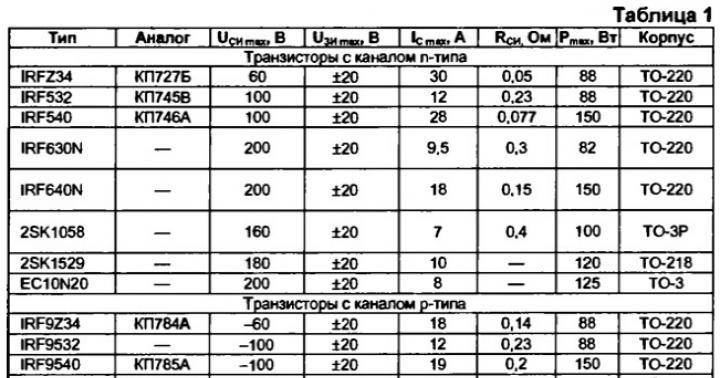
A field chip (like the one in the diagram or something similar) can be dug out from an old computer motherboard; usually there are several of them there at once. TL-ku, by the way, can also be taken from there.
Capacitor C1 is needed for the initial startup of the circuit when the switch is turned on (it briefly pulls the gate T1 to minus, which opens the transistor and powers the voltage divider R3, R2). Further, after charging C1, the voltage required to unlock the transistor is maintained by the TL431 microcircuit.
Attention! The IRF4905 transistor indicated in the diagram will perfectly protect three lithium-ion batteries connected in series, but is completely unsuitable for protecting one 3.7 Volt bank. It is said how to determine for yourself whether a field-effect transistor is suitable or not.
The downside of this circuit: in the event of a short circuit in the load (or too much current consumed), the field-effect transistor will not close immediately. The reaction time will depend on the capacitance of capacitor C1. And it is quite possible that during this time something will have time to burn out properly. A circuit that instantly responds to a short load under load is presented below: 
Switch SA1 is needed to “restart” the circuit after the protection has tripped. If the design of your device provides for removing the battery to charge it (in a separate charger), then this switch is not needed.
The resistance of resistor R1 must be such that the TL431 stabilizer reaches operating mode at a minimum battery voltage - it is selected in such a way that the anode-cathode current is at least 0.4 mA. This gives rise to another drawback of this circuit - after the protection is triggered, the circuit continues to consume energy from the battery. The current, although small, is quite enough to completely drain a small battery in just a couple of months.
The diagram below for self-made monitoring of the discharge of lithium batteries is free from this drawback. When the protection is triggered, the current consumed by the device is so small that my tester does not even detect it. 
Below is a more modern version of the lithium battery discharge limiter using the TL431 stabilizer. This, firstly, allows you to easily and simply set the desired response threshold, and secondly, the circuit has high temperature stability and clear shutdown. Clap and that's it! 
Getting TL-ku today is not a problem at all, they are sold for 5 kopecks per bunch. Resistor R1 does not need to be installed (in some cases it is even harmful). Trimmer R6, which sets the response voltage, can be replaced with a chain of constant resistors with selected resistances.
To exit the blocking mode, you need to charge the battery above the protection threshold, and then press the S1 “Reset” button.
The inconvenience of all the above schemes is that to resume operation of the schemes after going into protection, operator intervention is required (turn SA1 on and off or press a button). This is the price to pay for simplicity and low power consumption in lock mode.
The simplest li-ion overdischarge protection circuit, devoid of all disadvantages (well, almost all) is shown below: 
The principle of operation of this circuit is very similar to the first two (at the very beginning of the article), but there is no TL431 microcircuit, and therefore its own current consumption can be reduced to very small values - about ten microamps. A switch or reset button is also not needed; the circuit will automatically connect the battery to the load as soon as the voltage across it exceeds a preset threshold value.
Capacitor C1 suppresses false alarms when operating on a pulsed load. Any low-power diodes will do; it is their characteristics and quantity that determine the operating voltage of the circuit (you will have to select it locally).
Any suitable n-channel field effect transistor can be used. The main thing is that it can withstand the load current without straining and be able to open at low gate-source voltage. For example, P60N03LDG, IRLML6401 or similar (see).
The above circuit is good for everyone, but there is one unpleasant moment - the smooth closing of the field-effect transistor. This occurs due to the flatness of the initial section of the current-voltage characteristic of the diodes.
This drawback can be eliminated with the help of modern element base, namely with the help of micro-power voltage detectors (power monitors with extremely low power consumption). The next circuit for protecting lithium from deep discharge is presented below: 
MCP100 microcircuits are available in both DIP packages and planar versions. For our needs, a 3-volt option is suitable - MCP100T-300i/TT. Typical current consumption in blocking mode is 45 µA. The cost for small wholesale is about 16 rubles/piece.
It’s even better to use a BD4730 monitor instead of the MCP100, because it has a direct output and, therefore, it will be necessary to exclude transistor Q1 from the circuit (connect the output of the microcircuit directly to the gate of Q2 and resistor R2, while increasing R2 to 47 kOhm).
The circuit uses a micro-ohm p-channel MOSFET IRF7210, which easily switches currents of 10-12 A. The field switch is fully open already at a gate voltage of about 1.5 V, and in the open state it has negligible resistance (less than 0.01 Ohm)! In short, a very cool transistor. And, most importantly, not too expensive.
In my opinion, the last scheme is the closest to the ideal. If I had unlimited access to radio components, I would choose this one.
A small change in the circuit allows you to use an N-channel transistor (then it is connected to the negative load circuit): 
BD47xx power supply monitors (supervisors, detectors) are a whole line of microcircuits with response voltages from 1.9 to 4.6 V in steps of 100 mV, so you can always choose them to suit your purposes.
A small retreat
Any of the above circuits can be connected to a battery of several batteries (after some adjustment, of course). However, if the banks have different capacities, then the weakest of the batteries will constantly go into a deep discharge long before the circuit operates. Therefore, in such cases, it is always recommended to use batteries not only of the same capacity, but preferably from the same batch.
And although this protection has been working flawlessly in my metal detector for two years now, it would still be much more correct to monitor the voltage on each battery personally.
Always use your personal Li-ion battery discharge controller for each jar. Then any of your batteries will serve you happily ever after.
How to choose a suitable field-effect transistor
In all of the above schemes for protecting lithium-ion batteries from deep discharge, MOSFETs operating in switching mode are used. The same transistors are usually used in overcharge protection circuits, short-circuit protection circuits, and in other cases where load control is required.
Of course, in order for the circuit to work as it should, the field-effect transistor must meet certain requirements. First, we will decide on these requirements, and then we will take a couple of transistors and use their datasheets (technical characteristics) to determine whether they are suitable for us or not.
Attention! We will not consider the dynamic characteristics of FETs, such as switching speed, gate capacitance and maximum pulsed drain current. These parameters become critically important when the transistor operates at high frequencies (inverters, generators, PWM modulators, etc.), however, discussion of this topic is beyond the scope of this article.
So, we must immediately decide on the circuit that we want to assemble. Hence the first requirement for a field-effect transistor - it must be the right type(either N- or P-channel). This is the first.
Let's assume that the maximum current (load current or charge current - it doesn't matter) will not exceed 3A. This leads to the second requirement - a field worker must withstand such current for a long time.
Third. Let's say our circuit will protect the 18650 battery from deep discharge (one bank). Therefore, we can immediately decide on the operating voltages: from 3.0 to 4.3 Volts. Means, maximum permissible drain-source voltage U ds should be more than 4.3 Volts.
However, the last statement is true only if only one lithium battery bank is used (or several connected in parallel). If, to power your load, a battery of several batteries connected in series is used, then the maximum drain-source voltage of the transistor must exceed the total voltage of the entire battery.
Here is a picture explaining this point: 
As can be seen from the diagram, for a battery of 3 18650 batteries connected in series, in the protection circuits of each bank it is necessary to use field devices with a drain-to-source voltage U ds > 12.6V (in practice, you need to take it with some margin, for example, 10%).
At the same time, this means that the field-effect transistor must be able to open completely (or at least strongly enough) already at a gate-source voltage U gs of less than 3 Volts. In fact, it is better to focus on a lower voltage, for example, 2.5 Volts, so that there is a margin.
For a rough (initial) estimate, you can look in the datasheet at the “Cut-off voltage” indicator ( Gate Threshold Voltage) is the voltage at which the transistor is on the threshold of opening. This voltage is typically measured when the drain current reaches 250 µA.
It is clear that the transistor cannot be operated in this mode, because its output impedance is still too high, and it will simply burn out due to excess power. That's why The transistor cut-off voltage must be less than the operating voltage of the protection circuit. And the smaller it is, the better.
In practice, to protect one can of a lithium-ion battery, you should select a field-effect transistor with a cutoff voltage of no more than 1.5 - 2 Volts.
Thus, the main requirements for field-effect transistors are as follows:
- transistor type (p- or n-channel);
- maximum permissible drain current;
- the maximum permissible drain-source voltage U ds (remember how our batteries will be connected - in series or in parallel);
- low output resistance at a certain gate-source voltage U gs (to protect one Li-ion can, you should focus on 2.5 Volts);
- maximum permissible power dissipation.
Now let's look at specific examples. For example, we have at our disposal the transistors IRF4905, IRL2505 and IRLMS2002. Let's take a closer look at them.
Example 1 - IRF4905
 We open the datasheet and see that this is a transistor with a p-type channel (p-channel). If we are satisfied with this, we look further.
The maximum drain current is 74A. In excess, of course, but it fits.
Drain-source voltage - 55V. According to the conditions of the problem, we have only one bank of lithium, so the voltage is even greater than required.
Next, we are interested in the question of what the drain-source resistance will be when the opening voltage at the gate is 2.5V. We look at the datasheet and don’t immediately see this information. But we see that the cutoff voltage U gs(th) lies in the range of 2...4 Volts. We are categorically not happy with this.
The last requirement is not met, so discard the transistor.
Example 2 - IRL2505
 Here is his datasheet. We look and immediately see that this is a very powerful N-channel field device. Drain current - 104A, drain-source voltage - 55V. So far everything is fine.
Check the voltage V gs(th) - maximum 2.0 V. Excellent!
But let's see what resistance the transistor will have at a gate-source voltage = 2.5 volts. Let's look at the chart: 
It turns out that with a gate voltage of 2.5V and a current through the transistor of 3A, a voltage of 3V will drop across it. In accordance with Ohm's law, its resistance at this moment will be 3V/3A=1Ohm.
Thus, when the voltage on the battery bank is about 3 Volts, it simply cannot supply 3A to the load, since for this the total load resistance, together with the drain-source resistance of the transistor, must be 1 Ohm. And we only have one transistor that already has a resistance of 1 ohm.
In addition, with such an internal resistance and a given current, the transistor will release power (3 A) 2 * 3 Ohm = 9 W. Therefore, you will need to install a radiator (a TO-220 case without a radiator can dissipate somewhere around 0.5...1 W).
An additional alarm bell should be the fact that the minimum gate voltage for which the manufacturer specified the output resistance of the transistor is 4V.
This seems to hint that the operation of the field worker at a voltage U gs less than 4 V was not envisaged.
Considering all of the above, discard the transistor.
Example 3 - IRLMS2002
 So, let's take our third candidate out of the box. And immediately look at its performance characteristics.
N-type channel, let's say everything is in order.
Maximum drain current - 6.5 A. Suitable.
The maximum permissible drain-source voltage V dss = 20V. Great.
Cut-off voltage - max. 1.2 Volts. Still alright.
To find out the output resistance of this transistor, we don’t even have to look at the graphs (as we did in the previous case) - the required resistance is immediately given in the table just for our gate voltage.
When creating self-powered devices, care must be taken to protect the battery from deep discharge. It is enough to miss the moment once and allow the battery to be deeply discharged below the minimum voltage threshold and your battery will fail, or will lose part of its capacity and will be unable to operate at rated load currents.
In order to prevent cases of voltage drop below a critical level in the open circuit of the battery-consumer, protection circuits are installed, which consist of several units:
comparator and power switch.
Requirements for the protection circuit:
- low leakage current (self-consumption)
- switching currents comparable to the maximum permissible for the battery
This battery deep discharge protection circuit was assembled to protect a 6 volt acid-gel battery with a capacity of 4 ampere-hours, but it can also be configured to work with 12 volt batteries and higher, up to the supply voltage of the ne7555 chip. The prototype of this board was found in some magazine and slightly modified. Instead of a conventional zener diode, an adjustable zener diode TL431 was introduced, which allows you to adjust the cutoff voltage (load disconnection) in conjunction with adjusting the resistive divider R6/R7. From the 3rd leg of the 555 timer chip, the signal began to not illuminate the LED, but to open the n-p-n transistor, which in turn opens the power switch N-channel field-effect transistor. Pay your attention to the characteristics of this transistor, it must be designed to work with the expected load currents, and another important detail is gate opening voltage. If you are planning a circuit for a 6-volt battery, you need a field-effect transistor with an opening voltage of 5 volts n-channel logic level mosfet. Field-effect transistors for “general power” purposes with an opening voltage of 10-20 volts will not suit you, since when the voltage between the gate and source of the transistor is 5 volts, they will not be in saturation mode but in linear mode, which will lead to strong heat generation and failure .
Systems containing batteries require installation of equipment to protect the batteries from deep discharge. This avoids loss of storage capacity and shortened service life. Often, after 4-5 deep discharges, batteries cease to cope with the tasks assigned to them.
Price: from 3,728 rub.
Smart BatteryProtect removes non-essential loads from the battery, preventing it from being deeply discharged (which would damage the battery) or maintaining the necessary charge to turn the starter.
| Brand: | Victron |
|---|
Price: from 5,736 rub.
Victron Energy has developed unique intelligent battery protection devices BatteryProtect. The models are made in a waterproof case. This allows the equipment to be used not only indoors, but also on various vehicles (cars, boats, yachts, etc.).
Several modifications are available for order:
- BatteryProtect-65A;
- BatteryProtect-100A;
- BatteryProtect-220A.
Models differ from each other in:
- maximum continuous load current (65, 100 and 220 A);
- overall dimensions (40*48*106, 59*42*115 and 62*123*120 mm);
- peak current value (BP-65A - 300 A; BP-100A/220A - 600 A);
- weight (0.2, 0.5, and 0.8 kg);
- connection type (BP-65A - M6; BP-100A/220A - M8).
The rest of the technical specifications are identical.
- The input voltage range of the battery protectors is 6-35 V. The system voltage (12 or 24 V) is detected automatically.
- At full load, the equipment operates stably at temperatures from -40 to +40° C.
- By default, the manufacturer sets the following parameters for 12-volt and 24-volt devices: Engage - 12 V or 24 V; Disengage - 10.5 V or 21 V.
- Delays:
- alarm output - 12 s;
- reconnecting the load - 30 s;
- load disconnection - 90 s (with VE.Bus BMS occurs immediately).
- Current consumption - 1.5 mA (on), 0.6 mA (off).
- The maximum load on the alarm output is 50 mA.
The need to protect batteries from deep discharge
Deep battery discharge is the enemy of the battery. In a critical situation, the electrolyte density drops below the minimum permissible value, since most of the acid is deposited on the dioxide plates in the form of salts. Over time there are more and more of them.
A deep, long-term battery discharge leads to the fact that not all salt crystals dissolve when recharged from the charger. Battery capacity is significantly reduced. Even a short-term deep discharge of the battery takes about 3-5% of the service life of the equipment. The contact of the plates with the liquid is minimized, and the operation of the battery is disrupted.
That is why it is necessary to prevent the electrolyte density from decreasing below the permissible value. To do this, special protective devices are additionally attached to the batteries. The best such equipment is produced by Victron Energy.
When the battery voltage drops to a certain level, BatteryProtect will switch off the load automatically. This will leave the reserve needed to start the engine. The models we offer are highly reliable. The equipment does not include mechanical relays. The operating principle of these devices, which ensure preservation of battery life, is based on MOSFET switches.
Features of installation and programming of battery protection devices from deep discharge BatteryProtect
- It is recommended to entrust the installation of equipment to qualified specialists, since working with batteries is unsafe.
- Good quality connectors and wires of sufficient gauge should be used.
- The connection is made through a fuse with the appropriate rating.
- Live wires must not come into contact with the body of the device connected to the battery and/or the vehicle.
Incorrect connection may damage the electronic circuit. It is recommended to place devices designed to protect the battery from deep discharge in close proximity to the battery (up to 0.5 m). This will reduce voltage losses.
Remote control
A remote switch can be attached to the BatteryPortect battery protector. The delay before turning on/off the equipment is 1 s.
To organize the system, a low-current switch can be used, since the switching current is very small.
Programming
To start the reprogramming mode, you need to connect Input + and Program Input. After this, the LED will start blinking. The number of flashes indicates the program position. Once the required operating mode has been established, the connection should be deleted.
Benefits of BatteryProtect deep discharge battery protection devices
Programmable shutdown levels
The equipment can be configured to one of ten operating modes. Adjusts the voltage at which BatteryPortect will turn off the battery.

Surge protection
The load will automatically turn off if the voltage exceeds:
- 16V (for 12V systems);
- 32 V (for 24 V systems).
Alarm output delay
The alarm output is activated only if the voltage value is below the set level for more than 15 seconds. This avoids false signals. The battery protection device does not respond to engine starting.
The alarm is used to trigger a buzzer and/or light. Through this output you can connect a charger using an additional relay.
Load shedding delay
The load is switched off only 60 seconds after the alarm is activated. If during this time the voltage increases to a normal value, the system will continue to operate.
Remote control
Adding a remote switch to the system will greatly simplify the operation process.