Many car enthusiasts know very well that in order to extend the life of the battery, it is required periodically from the charger, and not from the car’s generator.
And the longer the battery life, the more often it needs to be charged to restore charge.
You can't do without chargers
To perform this operation, as already noted, chargers operating from a 220 V network are used. There are a lot of such devices on the automotive market, they may have various useful additional functions.
However, they all do the same job - convert alternating voltage 220 V into direct voltage - 13.8-14.4 V.
In some models, the charging current is manually adjusted, but there are also models with fully automatic operation.
Of all the disadvantages of purchased chargers, one can note their high cost, and the more sophisticated the device, the higher the price.
But many people have a large number of electrical appliances at hand, the components of which may well be suitable for creating a homemade charger.
Yes, a homemade device will not look as presentable as a purchased one, but its task is to charge the battery, and not to “show off” on a shelf.
One of the most important conditions when creating a charger is at least basic knowledge of electrical engineering and radio electronics, as well as the ability to hold a soldering iron in your hands and be able to use it correctly.
Memory from a tube TV
The first scheme will be, perhaps the simplest, and almost any car enthusiast can cope with it.
To make a simple charger, you only need two components - a transformer and a rectifier.
The main condition that the charger must meet is that the current output from the device must be 10% of the battery capacity.
That is, a 60 Ah battery is often used in passenger cars; based on this, the current output from the device should be 6 A. The voltage should be 13.8-14.2 V.
If someone has an old, unnecessary tube Soviet TV, then it is better to have a transformer than not to find one.
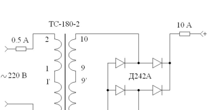
The schematic diagram of the TV charger looks like this.

Often, a TS-180 transformer was installed on such televisions. Its peculiarity was the presence of two secondary windings, 6.4 V each and a current strength of 4.7 A. The primary winding also consists of two parts.

First you will need to connect the windings in series. The convenience of working with such a transformer is that each of the winding terminals has its own designation.
To connect the secondary winding in series, you need to connect pins 9 and 9\’ together.
And to pins 10 and 10\’ - solder two pieces of copper wire. All wires that are soldered to the terminals must have a cross-section of at least 2.5 mm. sq.

As for the primary winding, for a series connection you need to connect pins 1 and 1\'. Wires with a plug for connecting to the network must be soldered to pins 2 and 2\’. At this point, work with the transformer is completed.


The diagram shows how the diodes should be connected - the wires coming from pins 10 and 10\', as well as the wires that will go to the battery, are soldered to the diode bridge.
Don't forget about fuses. It is recommended to install one of them on the “positive” terminal of the diode bridge. This fuse must be rated for a current of no more than 10 A. The second fuse (0.5 A) must be installed at terminal 2 of the transformer.
Before starting charging, it is better to check the functionality of the device and check its output parameters using an ammeter and voltmeter.
Sometimes it happens that the current is slightly higher than required, so some install a 12-volt incandescent lamp with a power of 21 to 60 watts in the circuit. This lamp will “take away” the excess current.
Microwave oven charger
Some car enthusiasts use a transformer from a broken microwave oven. But this transformer will need to be redone, since it is a step-up transformer, not a step-down transformer.
It is not necessary that the transformer be in good working order, since the secondary winding in it often burns out, which will still have to be removed during the creation of the device.

Remaking the transformer comes down to completely removing the secondary winding and winding a new one.
An insulated wire with a cross-section of at least 2.0 mm is used as a new winding. sq.
When winding, you need to decide on the number of turns. You can do this experimentally - wind 10 turns of a new wire around the core, then connect a voltmeter to its ends and power the transformer.
According to the voltmeter readings, it is determined what output voltage these 10 turns provide.
For example, measurements showed that there is 2.0 V at the output. This means that 12V at the output will provide 60 turns, and 13V will provide 65 turns. As you understand, 5 turns adds 1 volt.

It is worth pointing out that it is better to assemble such a charger with high quality, then place all the components in a case that can be made from scrap materials. Or mount it on a base.

Be sure to mark where the “positive” wire is and where the “negative” wire is, so as not to “over-plus” and damage the device.
Memory from the ATX power supply (for prepared ones)
A charger made from a computer power supply has a more complex circuit.
For the manufacture of the device, units with a power of at least 200 Watts of the AT or ATX models, which are controlled by a TL494 or KA7500 controller, are suitable. It is important that the power supply is fully operational. The ST-230WHF model from old PCs performed well.

A fragment of the circuit diagram of such a charger is presented below, and we will work on it.

In addition to the power supply, you will also need a potentiometer-regulator, a 27 kOhm trim resistor, two 5 W resistors (5WR2J) and a resistance of 0.2 Ohm or one C5-16MV.
The initial stage of work comes down to disconnecting everything unnecessary, which are the “-5 V”, “+5 V”, “-12 V” and “+12 V” wires.
The resistor indicated in the diagram as R1 (it supplies a voltage of +5 V to pin 1 of the TL494 controller) must be unsoldered, and a prepared 27 kOhm trimmer resistor must be soldered in its place. The +12 V bus must be connected to the upper terminal of this resistor.
Pin 16 of the controller should be disconnected from the common wire, and you also need to cut the connections of pins 14 and 15.

You need to install a potentiometer-regulator in the rear wall of the power supply housing (R10 in the diagram). It must be installed on an insulating plate so that it does not touch the block body.

The wiring for connecting to the network, as well as the wires for connecting the battery, should also be routed through this wall.
To ensure ease of adjustment of the device, from the existing two 5 W resistors on a separate board, you need to make a block of resistors connected in parallel, which will provide an output of 10 W with a resistance of 0.1 Ohm.
The article will tell you how to make a homemade one with your own hands. You can use absolutely any circuits, but the simplest manufacturing option is to remake a computer power supply. If you have such a block, it will be quite easy to find a use for it. To power motherboards, voltages of 5, 3.3, 12 Volts are used. As you understand, the voltage of interest to you is 12 Volts. The charger will allow you to charge batteries whose capacity ranges from 55 to 65 Ampere-hours. In other words, it is enough to recharge the batteries of most cars.
General view of the diagram
To make the alteration, you need to use the diagram presented in the article. made with your own hands from the power supply of a personal computer, allows you to control the charging current and voltage at the output. It is necessary to pay attention to the fact that there is protection against short circuit - a 10 Ampere fuse. But it is not necessary to install it, since most power supplies of personal computers have protection that turns off the device in the event of a short circuit. Therefore, charger circuits for batteries from computer power supplies are able to protect themselves from short circuits.
The PSI controller (designated DA1), as a rule, is used in the power supply of two types - KA7500 or TL494. Now a little theory. Can the computer's power supply charge the battery normally? The answer is yes, since lead batteries in most cars have a capacity of 55-65 Ampere-hour. And for normal charging it needs a current equal to 10% of the battery capacity - no more than 6.5 Amperes. If the power supply has a power of over 150 W, then its “+12 V” circuit is capable of delivering such current.
Initial stage of remodeling

To replicate a simple homemade battery charger, you need to slightly improve the power supply:
- Get rid of all unnecessary wires. Use a soldering iron to remove them so as not to interfere.
- Using the diagram given in the article, find a constant resistor R1, which must be unsoldered and in its place install a trimmer with a resistance of 27 kOhm. A constant voltage of “+12 V” must subsequently be applied to the upper contact of this resistor. Without this, the device will not be able to operate.
- The 16th pin of the microcircuit is disconnected from the minus.
- Next, you need to disconnect the 15th and 14th pins.
It turns out to be quite simple and homemade. You can use any circuits, but it’s easier to make it from a computer power supply - it’s lighter, easier to use, and more affordable. When compared with transformer devices, the mass of the devices differs significantly (as do the dimensions).
Charger adjustments

The back wall will now be the front; it is advisable to make it from a piece of material (textolite is ideal). On this wall it is necessary to install a charging current regulator, indicated in the diagram R10. It is best to use a current-sensing resistor as powerful as possible - take two with a power of 5 W and a resistance of 0.2 Ohm. But it all depends on the choice of battery charger circuit. Some designs do not require the use of high-power resistors.
When connecting them in parallel, the power is doubled, and the resistance becomes equal to 0.1 Ohm. On the front wall there are also indicators - a voltmeter and an ammeter, which allow you to monitor the relevant parameters of the charger. To fine-tune the charger, a trimming resistor is used, with which voltage is supplied to the 1st pin of the PHI controller.
Device requirements
Final assembly

Multi-core thin wires must be soldered to pins 1, 14, 15 and 16. Their insulation must be reliable so that heating does not occur under load, otherwise the homemade car charger will fail. After assembly, you need to set the voltage to about 14 Volts (+/-0.2 V) using a trimmer resistor. This is the voltage that is considered normal for charging batteries. Moreover, this value should be in idle mode (without a connected load).
You must install two alligator clips on the wires that connect to the battery. One is red, the other is black. These can be purchased at any hardware or auto parts store. This is how you get a simple homemade charger for a car battery. Connection diagrams: black is attached to the minus, and red to the plus. The charging process is completely automatic, no human intervention is required. But it is worth considering the main stages of this process.
Battery charging process

During the initial cycle, the voltmeter will show a voltage of approximately 12.4-12.5 V. If the battery has a capacity of 55 Ah, then you need to rotate the regulator until the ammeter shows a value of 5.5 Amperes. This means that the charging current is 5.5 A. As the battery charges, the current decreases and the voltage tends to a maximum. As a result, at the very end the current will be 0 and the voltage will be 14 V.
Regardless of the selection of circuits and designs of chargers used for manufacturing, the operating principle is largely similar. When the battery is fully charged, the device begins to compensate for the self-discharge current. Therefore, you do not risk the battery overcharging. Therefore, the charger can be connected to the battery for a day, a week, or even a month.

If you don’t have measuring instruments that you wouldn’t mind installing in the device, you can refuse them. But for this it is necessary to make a scale for the potentiometer - to indicate the position for the charging current values of 5.5 A and 6.5 A. Of course, the installed ammeter is much more convenient - you can visually observe the process of charging the battery. But a battery charger, made with your own hands without the use of equipment, can be easily used.
The battery receives a charge in the car from the generator while the vehicle is moving. However, as a safety element, the electrical circuit includes a monitoring relay, which ensures the output voltage from the generator at a level of 14 ±0.3V.
Since it is known that the sufficient level to fully and quickly charge the battery should be 14.5 V, it is obvious that the battery will need help to fill the entire capacity. In this case, you will either need a store-bought device, or you will need to make a charger for a car battery yourself at home.
In the warm season, even a half-discharged car battery will allow you to start the engine. During frosts, the situation is worse, because at negative temperatures the capacity decreases, and at the same time the inrush currents increase. Due to the increase in viscosity of cold oil, more force is required to spin the crankshaft. This means that in the cold season the battery needs maximum charge.
A large number of different options for homemade chargers allows you to choose a circuit for different levels of knowledge and skill of the manufacturer. There is even an option in which the car is manufactured using a powerful diode and an electric heater. A two-kilowatt heater connected to a 220 V household network, in a series circuit with a diode and battery, will give the latter a little more than 4 A of current. Overnight the circuit will “crank up” 15 kW, but the battery will receive a full charge. Although the overall efficiency of the system is unlikely to exceed 1%.
Those who are planning to make a simple do-it-yourself battery charger with transistors should be aware that such devices can overheat significantly. They also have problems with incorrect polarity and accidental short circuits.
For thyristor and triac circuits, the main problems are charge stability and noise. The downside is also radio interference, which can be eliminated with a ferrite filter, and polarity problems.
You can find many proposals for converting a computer power supply into a homemade battery charger. But you need to know that although the structural diagrams of these devices are similar, the electrical ones have significant differences. For proper rework, you will need sufficient experience in working with circuits. Blind copying during such alterations does not always lead to the desired result.
Schematic diagram of capacitors
The most interesting may be the capacitor circuit of a homemade charger for a car battery. It has high efficiency, does not overheat, produces a stable current, regardless of the battery charge level and possible problems with network fluctuations, and also withstands short-term short circuits.

Visually, the picture seems too cumbersome, but upon detailed analysis, all areas become clear. It is even equipped with a shutdown algorithm when the battery is fully charged.
Current limiter
For capacitor charging, current regulation and its stability are ensured by series connection of the transformer winding with ballast capacitors. In this case, a direct relationship is observed between the battery charging current and the capacitor capacity. Increasing the latter, we get a larger amperage.
Theoretically, this circuit can already work as a battery charger, but the problem will be its reliability. Weak contact with the battery electrodes will destroy unprotected transformers and capacitors.

Any student studying physics will be able to calculate the required capacitance for capacitors C=1/(2πvU). However, it will be faster to do this using a pre-prepared table:
You can reduce the number of capacitors in the circuit. To do this, they are connected in groups or using switches (toggle switches).
Reverse polarity protection in charger
To avoid problems when reversing the polarity of the contacts, the circuit contains relay P3. Incorrectly connected wires will be protected by the VD13 diode. It will not allow current to flow in the wrong direction and will not allow contact K3.1 to close; accordingly, the wrong charge will not flow to the battery.
If the polarity is correct, the relay will close and charging will begin. This circuit can be used on any type of homemade charging devices, even with thyristors or transistors.

Switch S3 controls the voltage in the circuit. The lower circuit gives the voltage value (V), and with the upper connection of the contacts we get the current level (A). If the device is connected only to the battery without being connected to a household network, then you can find out the battery voltage in the corresponding switch position. The head is an M24 microammeter.
Automation for homemade charging
We select a nine-volt circuit 142EN8G as the power supply for the amplifier. This choice is justified by its characteristics. Indeed, with temperature fluctuations of the board case even by ten degrees, the voltage fluctuations at the device output are reduced to an error of hundredths of a volt.
Self-shutdown is triggered at a voltage parameter of 15.5 V. This part of the circuit is marked A1.1. The fourth pin of the microcircuit (4) is connected to the divider R8, R7 where a voltage of 4.5 V is output to it. The other divider is connected to resistors R4-R5-R6. As a setting for this circuit, the adjustment of resistor R5 is used to indicate the level of excess. Using R9 in the microcircuit, the lower level of switching on the device is controlled, which is carried out at 12.5 V. Resistor R9 and diode VD7 provide a voltage range for uninterrupted charging operation.

The operating algorithm of the circuit is quite simple. By connecting to the charger, the voltage level is monitored. If it is below 16.5 V, then the circuit sends a command to open transistor VT1, which, in turn, starts the connection of relay P1. After this, the primary winding of the installed transformer is connected, and the battery charging process is started.
After reaching the full capacity and obtaining the output voltage parameter at a level of 16.5 V, the voltage in the circuit is reduced in order to keep transistor VT1 open. The relay switches off. The current supply to the terminals is reduced to half an amp. The charging cycle starts again only after the voltage at the battery terminals drops to 12.5 V, then the charging supply is resumed.
This is how the machine controls the possibility of not recharging the battery. The circuit can be left in working condition even for several months. This option will be especially relevant for those who use the car seasonally.
Charger layout
The body of such a device can be a VZ-38 milliammeter. We remove unnecessary insides, leaving only the dial indicator. We install everything except the machine using a hinged method.
The electrical appliance consists of a pair of panels (front and back), which are fixed using perforated carbon horizontal beams. Through such holes it is convenient to attach any structural elements. A two-millimeter aluminum plate is used to position the power transformer. It is attached with self-tapping screws to the bottom of the device.

A fiberglass plate with relays and capacitors is mounted on the upper plane. A circuit board with automation is also attached to the perforated ribs. Relays and capacitors of this element are connected using a standard connector.
A radiator on the rear wall will help reduce the heating of the diodes. It would be appropriate to place fuses and a powerful plug in this area. It can be taken from the computer's power supply. To clamp the power diodes we use two clamping bars. Their use will allow rational use of space and reduce heat generation inside the unit.

It is advisable to carry out installation using intuitive wire colors. We take red as positive, blue for negative, and highlight the alternating voltage using, for example, brown. The cross-section in all cases should be more than 1 mm.

The ammeter readings are calibrated using a shunt. One of its ends is soldered to the contact of relay P3, and the second is soldered to the positive output terminal.
Components
Let's look at the insides of the device, which form the basis of the charger.
Printed circuit board
Fiberglass is the basis for the printed circuit board, which acts as protection against voltage surges and connection problems. The image is formed with a step of 2.5 mm. Without any problems, this circuit can be made at home.
 Location of elements in reality
  Soldering layout
  Board for manual soldering
There is even a schematic plan with highlighted elements on it. A clean image is used to apply it to a substrate using powder printing on laser printers. For the manual method of applying tracks, another image is suitable.
Graduation scale
The indication of the installed VZ-38 milliammeter does not correspond to the actual readings given by the device. To make adjustments and correct graduation, it is necessary to glue a new scale to the base of the indicator behind the arrow.

The updated information will correspond to reality with an accuracy of 0.2 V.
Connecting cables
The contacts that will connect to the battery must have a spring clip with teeth (“crocodile”) at the ends. To distinguish between the poles, it is advisable to immediately select the positive part in red, and take the negative cable with a clamp in blue or black.

The cable cross-section must be more than 1 mm. To connect to a household network, a standard non-separable cable with a plug from any old office equipment is used.
Electrical components for homemade battery charging
TN 61-220 is suitable as a power transformer, because the output current will be at the level of 6 A. For capacitors, the voltage must be more than 350 V. For the circuit for C4 to C9 we take the MBGC type. Diodes from 2 to 5 are needed to withstand a ten-amp current. The 11th and 7th can be taken with any impulse ones. VD1 is an LED, and the 9th one can be an analogue of KIPD29.
For the rest, you need to focus on the input parameter that allows a current of 1A. In relay P1, you can use two LEDs with different color characteristics, or you can use a binary LED.

The AN6551 operational amplifier can be replaced by the domestic analogue KR1005UD1. They can be found in old audio amplifiers. The first and second relays are selected from the range of 9-12 V and a current of 1 A. For several contact groups in the relay device, we use paralleling.
Setup and launch
If everything is done without errors, the circuit will work immediately. We adjust the threshold voltage using resistor R5. It will help transfer charging to the correct low current mode.
I know that I’ve already gotten all sorts of different chargers, but I couldn’t help but repeat an improved copy of the thyristor charger for car batteries. Refinement of this circuit makes it possible to no longer monitor the state of charge of the battery, also provides protection against polarity reversal, and also saves the old parameters
On the left in the pink frame is a well-known circuit of a phase-pulse current regulator; you can read more about the advantages of this circuit
The right side of the diagram shows a car battery voltage limiter. The point of this modification is that when the voltage on the battery reaches 14.4V, the voltage from this part of the circuit blocks the supply of pulses to the left side of the circuit through transistor Q3 and charging is completed.
I laid out the circuit as I found it, and on the printed circuit board I slightly changed the values of the divider with the trimmer
This is the printed circuit board I got in the SprintLayout project

The divider with trimmer on the board has changed, as mentioned above, and also added another resistor to switch voltages between 14.4V-15.2V. This voltage of 15.2V is necessary for charging calcium car batteries
There are three LED indicators on the board: Power, Battery connected, Polarity reversal. I recommend putting the first two green, the third LED red. The variable resistor of the current regulator is installed on the printed circuit board, the thyristor and diode bridge are placed on the radiator.
I'll post a couple of photos of the assembled boards, but not in the case yet. There are also no tests of a charger for car batteries yet. I'll post the rest of the photos once I'm in the garage.


I also started drawing the front panel in the same application, but while I’m waiting for a parcel from China, I haven’t started working on the panel yet

I also found on the Internet a table of battery voltages at different states of charge, maybe it will be useful to someone

An article about another simple charger would be interesting.
In order not to miss the latest updates in the workshop, subscribe to updates in In contact with or Odnoklassniki, you can also subscribe to email updates in the column on the right
Don’t want to delve into the routine of radio electronics? I recommend paying attention to the proposals of our Chinese friends. For a very reasonable price you can purchase quite high-quality chargers
A simple charger with an LED charging indicator, green battery is charging, red battery is charged.
There is short circuit protection and reverse polarity protection. Perfect for charging Moto batteries with a capacity of up to 20A/h; a 9A/h battery will charge in 7 hours, 20A/h in 16 hours. The price for this charger is only 403 rubles, free delivery
This type of charger is capable of automatically charging almost any type of 12V car and motorcycle batteries up to 80A/H. It has a unique charging method in three stages: 1. Constant current charging, 2. Constant voltage charging, 3. Drop charging up to 100%.
There are two indicators on the front panel, the first indicates the voltage and charging percentage, the second indicates the charging current.
Quite a high-quality device for home needs, the price is just RUR 781.96, free delivery. At the time of writing these lines number of orders 1392, grade 4.8 out of 5. When ordering, do not forget to indicate Eurofork
Charger for a wide variety of 12-24V battery types with current up to 10A and peak current 12A. Able to charge Helium batteries and SA\SA. The charging technology is the same as the previous one in three stages. The charger is capable of charging both automatically and manually. The panel has an LCD indicator indicating voltage, charging current and charging percentage.
A good device if you need to charge all possible types of batteries of any capacity, up to 150Ah
Long-term use of the car leads to the fact that the generator stops charging the battery. As a result, the car will no longer start. To revive the car you need a charger. In addition, lead-acid batteries are highly sensitive to temperatures. Therefore, problems may arise with their operation if the temperature outside is sub-zero.
A car charger is not particularly technically complex. To collect it you don’t need to have any highly specialized knowledge, just perseverance and ingenuity. Of course, you will need certain parts, but they can easily be purchased on the radio market for almost nothing.
Types of chargers for cars
Science does not stand still. Technologies are developing at an incredible speed; it is not surprising that transformer chargers are gradually disappearing from the market, and they are being replaced by pulsed and automatic chargers.
The pulse charger for the car has compact dimensions. His easy to use, and unlike transformer type devices of this class provide a full battery charge. The charging process takes place in two stages: first at constant voltage, then at current. The design consists of similar circuits.
The automatic car charger is extremely easy to use. In fact, this is a multifunctional diagnostic center, which is extremely difficult to assemble on your own.
The most advanced devices of this class will notify you with a signal if the poles are connected incorrectly. Moreover, the power supply will not even start. You cannot ignore the diagnostic functions of the device. It is able to measure battery capacity and even charge level.
Electrical circuits have a timer. Therefore, an automatic car charger allows for various types of charging:
- full,
- fast,
- restorative.
Once the automatic car charger has finished charging, a beep will sound and the current will automatically stop flowing.
Three ways to make a car charger with your own hands
How to make a charger from a computer block

Old computers are not uncommon. Some people leave them out of a sense of nostalgia, while others hope to use serviceable components somewhere. If you don’t have an old desktop computer at home, it’s okay. Second-hand The power supply can be purchased for 200-300 rubles.
Power supplies from desktop computers are ideal for creating any chargers. The controller used here is the TL494 chip or a similar KA7500 chip.
The power supply for the charger must be 150 W or higher. All wires from sources -5, -12, +5, +12 V are soldered off. The same is done with resistor R1. It needs to be replaced with a trim resistor. In this case, the value of the latter should be 27 Ohms.
The operating diagram of a car charger from a power supply is extremely simple. The voltage from the bus marked at +12 V is transmitted to the upper pin. In this case, pins 14 and 15 are simply cut off due to their uselessness.
Important! The only pin that needs to be left is the sixteenth one. It is adjacent to the main wire. But at the same time it needs to be turned off.
A potentiometer-regulator R10 should be installed on the rear wall of the power supply. You also need to run two cords: one for connecting the terminals, the other for the network. Additionally, you need to prepare a block of resistors. It will allow for adjustments.

To make the block described above, you will need two current measuring resistors. It is best to use 5W8R2J. A power of 5 W is quite enough. The block resistance will be 0.1 Ohm, and the total power will be 10 W.
To configure, you will need a trim resistor. It is attached to the same board. Part of the print track is first removed. This will eliminate the possibility of communication between the case and the main circuit, and will also significantly increase the safety of the car charger.
Before as solder pins 1, 14-16, they must first be tinned. Multi-core thin wires are soldered. Full charge is determined by the open circuit voltage. The standard range is 13.8-14.2 V.
The full charge is set by a variable resistor. It is important that potentiometer R10 is in the middle position. To connect the output to the terminals, special clamps are installed at the ends. It is best to use the crocodile type.
The insulating tubes of the clamps must be made in different colors. Traditionally, red is a plus, blue is a minus. But you can choose any colors you like. This is not important.
Important! If you mix up the wires, it will damage the device.

To save time and money when assembling a charger for a car, you can eliminate the volt and ammeter from the design. The initial current can be set using potentiometer R10. Recommended value is 5.5 and 6.5 A.
Charger from adapter
The best option for creating a car charger is a 12-volt adapter. But when choosing a voltage, you must first consider the battery parameters.
The adapter wire must be cut at the end and exposed. About 5-7 centimeters will be enough for comfortable work. Wires with opposite charges must be laid at a distance of 40 centimeters from each other. A “crocodile” is put on the end of each one.
The clamps are connected to the battery in sequential order. Plus to plus, minus to minus. After that, all you need to do is turn on the adapter. This is one of the simplest schemes for creating a charger for a car with your own hands.
Important! During the charging process, you need to ensure that the battery does not overheat. If this happens, the process must be interrupted immediately to avoid damage to the battery.
Everything ingenious is simple or a car charger made from a light bulb and a diode

Everything you need to create this charger can be found at home. The main element of the design will be an ordinary light bulb. Moreover, its power should not be higher than 200 W.
Important! The more power, the faster the battery will charge.
When charging, some care must be taken. You should not charge a low-capacity battery with a 200-watt light bulb. Most likely this will lead to it simply boiling. There is a simple calculation formula that will help you choose the optimal light bulb power for your battery.
You will also need a semiconductor diode that will conduct electricity in only one direction. It can be made from a regular laptop charger. The final element of the design will be a wire with terminals and a plug.
It is very important to follow safety rules when creating a charger for a car. First, always unplug the circuit before touching any of the elements with your hand. Secondly, all contacts must be carefully isolated. There should be no exposed wires.
When assembling the circuit, all elements are connected in series: lamp, diode, battery. It is important to know the polarity of the diode in order to connect everything correctly. For greater safety, use rubber gloves.

When assembling the circuit, pay special attention to the diode. There is usually an arrow on it that points to the plus. Since it only allows electricity to pass in one direction, this is extremely important. You can use a tester to check the polarity of the terminals.
If everything is configured and connected correctly, the light will light at half a channel. If there is no light, it means you did something wrong or the battery is completely discharged.
The charging process itself takes about 6-8 hours. After this time period, the car charger must be disconnected from the network to avoid overheating of the battery.
If you urgently need to recharge the battery, the process can be accelerated. The main thing is that the diode is powerful enough. You will also need a heater. All elements are connected into one circuit. The efficiency of this charging method is only 1%, but the speed is many times higher.
Results
The simplest car charger can be assembled with your own hands in a few hours. At the same time, a set of necessary materials can be found in every home. More complex devices require more time to create, but they have increased reliability and a good level of security.