The engine is perhaps the most important unit in a car. It is he who generates torque for further movement of the car. The design of the internal combustion engine is based on the crank mechanism. Its purpose and design will be discussed in our article today.
Design
So what is this element in the engine?
This mechanism perceives the energy of gas pressure and converts it into mechanical work. The crankshaft of an internal combustion engine combines several components, namely:
- piston;
- connecting rod;
- crankshaft with liners;
- rings and bushings.
Together they form a cylinder-piston group. Each part of the crank mechanism does its job. Moreover, the elements are interconnected. Each part has its own device and purpose. The crank mechanism must withstand increased shock and temperature loads. This determines the reliability of the power unit as a whole. Next, we will talk in detail about each of the components listed above.
Piston
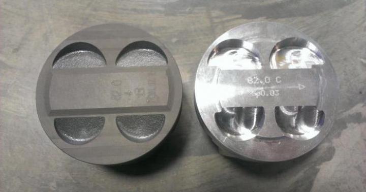
This part of the crank mechanism perceives the pressure of expanding gases after ignition of the combustible mixture in the chamber. The piston is made of aluminum alloys and carries out reciprocating movements in the block sleeve. The piston design combines a head and a skirt. The first can have different shapes: concave, flat or convex.

On 16-valve VAZ engines, pistons with recesses are often used. They serve to prevent the piston head from colliding with the valves in the event of a timing belt break.
Rings
The design also includes rings:
- oil scraper;
- compression (two pieces).
The latter prevent gas leaks into the engine crankcase. And the first serve to remove excess oil that remains on the cylinder walls during the piston stroke. In order for the piston to connect to the connecting rod (we will talk about it below), its design also includes bosses.
connecting rod
The operation of the crank mechanism cannot do without this element. The connecting rod transmits pushing forces from the piston to the crankshaft. Data and mechanisms are usually made by forging or stamping. But sports engines use titanium cast elements. They are more resistant to loads and do not deform in the event of a large shock.

What is the structure and purpose of the crank mechanism? Structurally, the connecting rod consists of three parts:
- top head;
- rod;
- lower head.
At the top, this element is connected to the piston using a finger. The rotation of the part is carried out in the same bosses. This type of finger is called a floating finger. The rod of the connecting rod has an I-section. The lower part is collapsible. This is necessary in order to remove it from the crankshaft in case of malfunctions. The lower head is connected to the crankshaft journal. We will look at the device of the latter right now.
Crankshaft
This element is the main component in the design of the crank mechanism. Its purpose is as follows. absorbs loads from the connecting rod. Next, it converts them into torque, which is subsequently transmitted to the box through the clutch mechanism. A flywheel is attached to the end of the shaft. It is the final part in the engine design. It can be one- or two-mass. At the end it has a gear rim. It is needed to engage with the starter gear when the engine starts. As for the shaft itself, it is made of high-strength steel and cast iron. The element consists of connecting rod and main journals, which are connected by “cheeks”. The latter rotate in liners (sliding bearings) and can be detachable. There are holes inside the cheeks and necks for oil supply. The lubricant penetrates under pressure from 1 to 5 bar, depending on the load of the internal combustion engine.

Shaft imbalance may occur while the engine is running. To prevent this, the design includes a torsional vibration damper. It consists of two metal rings that are connected through an elastic medium (motor oil). There is a belt pulley on the outer ring of the damper.
Types of CPG
At the moment, there are several types of cylinder-piston group. The most popular is the in-line design. It is used on all 4-cylinder engines. There are also in-line “sixes” and even “eights”. This design involves placing the cylinder axis in one plane. They are characterized by high balance and low vibration.
There is also a V-shaped design, which came from the Americans. A diagram of the V-8 crank mechanism is shown in the photo below.

As you can see, here the cylinders are located in two planes. They are usually at an angle of 75 to 90 degrees relative to each other. Thanks to this design, you can significantly save space in the engine compartment. An example is the 6-cylinder engines from Opel C25XE. This V-twin engine fits transversely under the hood without any problems. If you take the inline six from a front-wheel drive Volvo, it will noticeably take up space under the hood.
But for compactness you have to pay less vibration resistance. Another cylinder placement scheme is opposed. Practiced on Japanese Subaru cars. The cylinder axes are also located in two planes. But unlike the V-shaped design, here they are at an angle of 180 degrees. The main advantages are a low center of gravity and excellent balance. But such engines are very expensive to produce.

Repair and maintenance of the crank mechanism
Maintenance of any automatic transmission only involves regular replacement of the engine oil. In case of repair, attention is paid to the following elements:
- Piston rings. When they occur, they are replaced with new ones.
- Crankshaft bearings. If the sliding bearing is significantly worn out or rotated, replace it with a new one.
- Piston pins. They also have production.
- To the pistons themselves. When detonation occurs, the head can burn out, which entails a decrease in compression, tripping, oil consumption and other problems with the engine.
Often, such malfunctions occur when the oil and filter are not changed in a timely manner, as well as when low-octane gasoline is used. Also, crankshaft repair may be needed under constant loads and high mileage. Parts of machines and mechanisms usually have a high safety margin. But there are cases when, already at 120 thousand kilometers, valves and pistons burned out. All this is a consequence of untimely maintenance of the power unit.
So, we found out what the crank mechanism is and what elements it consists of.
It's no secret that the main mechanism that sets a car in motion is the engine. Those. we can say that the power unit is the heart of any car. But without a crank mechanism, the operation of an internal combustion engine is impossible. It turns out that the crankshaft is nothing more than the heart of the engine. And it is this mechanism that Auto-Gurman.ru will talk about below.Crank mechanism. What it is?
KShM is a mechanism that converts one movement into another. That is, for example, it can transform rotation into rocking, translational-pushing and other movements.The crank mechanism can be found not only in piston internal combustion engines, but also in various compressors, pumps and other mechanical devices.
Today, the KShM is the most popular mechanism for converting one movement into another. Therefore, now it is worth considering its device.
KShM device
The main elements of the mechanism are divided into two groups:1. Movable;
2. Fixed.
The moving elements are pistons, piston rings, pins, crankshaft with flywheel and connecting rod. All piston elements are a piston group.
The fixed elements are the connecting parts, the cylinder block and its head, as well as the pan and crankcase with crankshaft bearings.
Let's look at each element in more detail.
Piston
The piston is an element of the crankshaft that changes the gas pressure. Such changes are carried out by its reciprocating movement.
Externally, the piston is made in the form of a cylinder made of aluminum alloy. The main parts of the piston are the bottom, skirt and head. Each detail performs its function. The bottom has a combustion chamber. The head contains special threaded grooves in which the piston rings are located. The main purpose of the rings is to protect the engine crankcase from gases and remove excess oil from the cylinder walls. The skirt inside has a piston pin, which is placed in this element of the mechanism due to special bosses.
The skirt contains two bosses to accommodate the piston with the connecting rod of the pin.
connecting rod
The connecting rod is the main element of the crank mechanism for transmitting piston force to the crankshaft. This part can be forged from steel or titanium.
By design, the connecting rod consists of a rod with an I-section, as well as heads (upper and lower). The upper head, like the skirt, has bosses in which the piston pin is located, and the lower collapsible head ensures high accuracy of joining parts.
Block and cylinder head
The cylinder block has special cooling jackets, mounting points for the main components and instruments, as well as a bed for the crankshaft and camshaft bearings.
The block itself and the head are cast from cast iron or aluminum. Well, the main purpose of the block is to direct the pistons.
As for the cylinder head, it has inside it special holes for spark plugs, intake and exhaust channels, bushings, as well as a combustion chamber and pressed seats.
Crankshaft
The crankshaft is an element for receiving forces from the connecting rod, which further converts these forces into torque. Most often it is made of cast iron or steel. It consists of root and connecting rod journals. The necks are connected by special cheeks. Their main working process takes place directly in the plain bearings. The cheeks and necks have special holes designed to supply oil.
Flywheel
The flywheel is located at the end of the crankshaft. It plays one of the main roles in the operation of the engine - it participates in starting the internal combustion engine through the starter.
Here are the main elements of the crank mechanism. Now Auto-Gurman.ru wants to introduce you to the operating principle of the KShM.
Crank mechanism: operating principle
And so, the piston is at the maximum distance from the crankshaft. The crank and connecting rod line up in one line. At this moment, fuel enters the cylinder and it begins to burn. Combustion products, namely expanding gases, move the piston towards the crankshaft. At the same time, the connecting rod also moves, the lower head of which rotates the crankshaft 180°. After this, the connecting rod and its head move and rotate in the opposite direction, returning to its original position. The piston also returns back to its original place. And this process of work goes in circles.As you can see, the crank mechanism is the main mechanism of the engine, on the operation of which the health of the car depends. Therefore, you should always monitor this unit and, if there are any signs of a malfunction, fix it as quickly as possible, since the result of a crankshaft failure can be a complete failure of the engine, the repair of which will greatly affect your personal budget.
With controlled combustion of fuel in the internal combustion engine of a car, the pistons are given a reciprocating motion. To convert it into torque, the KShM unit is used - a crank mechanism, hinged to the pistons and crankshaft. There are few main faults, but elimination requires complete disassembly of the engine.
KShM design
Unlike other car components, the design of the crank mechanism conventionally includes part of the piston group and the crankshaft. The crankshaft consists of moving parts and fixed elements. They have one or more degrees of freedom:
- connecting rod and piston;
- compression, retaining and oil scraper rings;
- piston pin and retaining ring;
- liners, mounting bolt and connecting rod cover;
- flywheel and crankshaft;
- counterweight and connecting rod journals, main ones;
- inserts.
Fixed elements include the cylinder head and block.
Depending on the design of the internal combustion engine and the number of cylinders, the kinematics of the crank mechanism changes slightly:
- in an in-line engine, the plane of the crankshaft and cylinders completely coincide;
- in the VR-shaped motor there is a shift at an angle of 15 degrees;
- in the W-shaped drive, the displacement value reaches 72 degrees.
In other words, in an in-line engine, the working cycle is carried out alternately by 4 cylinders, which allows the load on the crankshaft to be evenly distributed. To achieve compact dimensions, internal combustion engines with a large number of cylinders are placed in a V-shape. This also makes it possible to soften the load on the crankshaft by dissipating part of the energy.

Sectional drawing of the KShM

To ensure that the characteristics of the crank mechanism are stable during overloads (high temperature, high pressure and speed, difficulties with lubrication supply), instead of ball/roller bearings, sliding elements with connecting rod and main bearings are used. The unevenness of the angular speeds of the shaft in individual cycles is smoothed out by a massive flywheel due to the inertia of this part.
Operating principle and purpose
Unlike an electric motor, the operating principle of a crankshaft in internal combustion engines is much more complicated:
- the pistons are alternately pushed out of the cylinders when the fuel mixture is ignited;
- connecting rod parts of complex configuration are hinged inside them;
- the crankshaft has a U-shaped reciprocal seating surface for the lower head of the connecting rod, which ensures displacement from the axis of rotation of the shaft;
- due to the fixed distance between the piston and the crankshaft, the connecting rod describes an amplitude in the form of a figure eight, due to which the translational movement from the cylinders is converted into torque on the shaft.
The main purpose of the consumable elements of the flywheel (liners, bushings, rings) is to increase the service life of this unit. Since the number of cylinders reaches 16 in modern cars, the design and operation of the cylinder head mechanism must be perfectly balanced.
Breakdowns and problems of the crank mechanism
Almost all parts of the crankshaft drive are friction pairs, which is clearly confirmed by the diagram of the kinematics of the vehicle drive. If the diagnosis of this internal combustion drive mechanism reveals malfunctions, a major overhaul of the engine is necessary, since it is completely disassembled.
Technical features of crankshaft drive malfunctions include wear of friction parts. The main breakdowns are:
- stuck rings on the pistons - due to high metal production, play appears, misalignment occurs and the piston becomes jammed inside the cylinder;
- wear of the piston pins - instead of a fixed size between the crankshaft/piston, the distance becomes floating, the torque characteristics change;
- development of the piston group - the cylinder mirror or piston surface is ground off, the characteristics of the internal combustion engine change;
- Bearing wear – the connecting rod or main bearings are worn down, causing shock loads on the shaft.
The main causes of malfunctions are prolonged loads, lack of maintenance, poor quality of lubrication or exhaustion of the drive life.

Position of piston rings
The specified malfunctions of the crank mechanism are diagnosed based on the following symptoms:
- interruptions in engine operation;
- a constant decrease in the lubricant level in the crankcase;
- exhaust gases take on a blue tint.
The breakdown cannot be repaired at home, as it requires a highly qualified technician and complete disassembly of the engine.
Wear of pistons and pins
These specific malfunctions of the crank mechanism are identified by the following signs:
- fingers - regardless of the operating mode of the engine, a loud knocking sound is heard in the upper part of the cylinder block, which disappears when the spark plug is unscrewed, and increases as the shaft speed increases;
- pistons - blue exhaust, knocking sound similar to the previous case, but only at idle, after warming up it usually disappears.
After diagnosing this malfunction, a major overhaul of the internal combustion engine is required.

Wear of connecting rod and main bearings
Repair of the crank mechanism will inevitably be required when the bearing life is exhausted, as evidenced by the following factors:
- connecting rod bearing - a warning light indicates insufficient lubricant pressure, a dull, floating knocking sound comes from the middle part of the cylinder block;
- main bearing - the warning light lights up, indicating low oil pressure, a dull knock occurs in the lower part of the cylinder block.
By analogy with the previous options, it will not be possible to do without major repairs.
Methods for diagnosing CVS
The above methods for identifying causes are not highly accurate. They serve as a reason for a trip to a service station, where a qualified diagnosis of the crank combination mechanism can be carried out by craftsmen with the necessary experience and practice. They have a kinematics drawing with exact dimensions, tolerances and fits. They have the necessary equipment for this.
Preliminary for knock detection
Since repair of the crank mechanism is an expensive engine overhaul operation, at the initial stage the service station technician positions knocks and noises inside the cylinder block. For this, a stethoscope is used (usually a modification of KI-1154 from the manufacturer Ekranas). The research technology is as follows:
- the working surface of the stethoscope leans against the walls of the BC at different levels (in the working area of the connecting rod and crank bearings);
- the engine warms up to a coolant temperature of 75 - 80 degrees;
- the speed increases smoothly at first, then the operating mode changes sharply;
- knocks are heard only when a gap of more than 0.1 - 0.2 mm occurs.
The nature of the knock is noticeable only to a professional:
- the pistons on the cylinder make clicking sounds when the engine is cold;
- a ringing sound of metal on metal with a sharp increase in speed is produced by the piston pin, less often with an incorrectly set (advanced) ignition angle;
- main bearings sound in low pitch;
- The sound of the connecting rod bearings is a little sharper.
Attention: This diagnostic technique is also not final. Allows the technician to identify existing defects with a guarantee that disassembling the internal combustion engine is still necessary to replace consumables.
Measuring total gaps in mates
Typically, maintenance of the crank mechanism is carried out using the KI-11140 installation to determine the clearance in the crankshaft.
In this case, you do not need to remove the oil pan and start the engine. The gaps in the connecting rod heads are measured in total:
- the piston of the diagnosed cylinder is positioned at the top “dead center”;
- the crankshaft is locked, the device is fixed in place of the nozzle;
- the rod presses against the bottom of the piston and is clamped with a screw;
- the compressor installation is connected to the fitting, a vacuum of -0.06 MPa and a pressure of the same value are created;
- after 2 – 3 cycles of supplying the specified pressure and vacuum, the indicator readings stabilize;
- then the indicator is adjusted to mark “0” in the space above the piston at pressure;
- after which negative pressure is applied to it.
The total gaps are measured at least three times, the average value is obtained, and compared with the permissible operating standards from the tables.
Determining the volume of gas breaking into the crankcase
The existing assembly of the crank mechanism of a car is not suitable for operation if checking the escaping gases revealed a large amount of it in the crankcase. Measurements are made with the KI-4887-I device in the following way:
- the gas flow meter is connected to the crankcase cavity and to the muffler or vacuum unit;
- the engine switches to “under load” mode;
- escaping gases change the readings of the device by the amount of their volume passing per unit time.
With significant wear of the internal combustion engine, the flow rate may exceed 120 l/min; additional adjustments of the flow meter are required. After disconnecting the crankcase ventilation system, all additional openings must be closed with plugs/plugs.

Oil pressure measurement
The operating crank mechanism assembly is considered suitable for use if the oil pressure check meets the standard. Measurements are carried out with a KI-5472 device, consisting of a sleeve and a pressure gauge:
- the standard pressure gauge is twisted from the oil filter;
- a device is attached in its place;
- the engine warms up to 70 - 80 degrees;
- The value of the main pressure at idle speed is recorded.
The extremely simple general design of the lubrication system and the CI device makes it possible to reduce diagnostic time.
For a carburetor-type internal combustion engine, compression within 0.7 MPa is considered normal. Therefore, in some cases, a service station diagnostician measures the compression of a warm engine. In this case, the difference in cylinder readings cannot exceed 0.1 MPa.
Repair technology
The main purpose of overhauling a crankshaft is to restore the service life of the piston group and crankshaft. To do this, the seats are restored, fingers and liners are replaced.

Pistons and pins
The piston, which is conventionally included in the crank mechanism of a car engine, is made of aluminum alloys. The finger is made of alloy steel and wears out less.
The pistons have their mirror and the geometry of the grooves for the rings and bosses, inside of which the pin is located, restored. The dimensions of the piston pin are selected at an air temperature in the workshop of 20 degrees, depending on the size group of the piston.
Connecting rod repair
Connecting rods are mainly made from steel 40G, 40X or St45; the following are considered characteristic defects:
- production of metal seats;
- hole wear;
- change in geometry (twisting and bending).
The kinematic element of the mechanism is rejected in case of emergency bending, breakage and crack opening. In other cases, bending and twisting are eliminated by heating to 500 degrees to relieve internal stress. The seating surfaces are milled and then ground to the next resize.
After which, the operation of the crank mechanism again satisfies the requirements of GOST regulations. It is prohibited to remove a metal layer larger than 0.2 - 0.4 mm for diesel engines and carburetor internal combustion engines, respectively. Otherwise, the kinematic diagram of the unit is disrupted.

Crankshaft restoration
The main nuances of crankshaft repair are:
- the part is made of high-strength magnesium cast iron, DR-U, 50T, 40X or St45 steels;
- the main defects are bending and wear of steel of the seats;
- keyways wear out less frequently, threads are damaged, and cracks open;
- An assembly of a crank mechanism with worn-out seating surfaces and damaged threads is considered repairable;
- cracks larger than 3 mm lead to crankshaft rejection.
After washing the oil channels and external surfaces, the product is examined with a flaw detector. The excavation is restored by fusing Sv-18KhGSA wire with a groove for repair parameters. Keyways are milled to a specified finish. In this case, the gear installation diagram must be observed.
After grinding, the crankshaft is balanced on a dynamic installation BM-U4 or KI-4274.
Thus, the crank mechanism of the crankshaft is easier and cheaper to maintain in working condition. To do this, you need to undergo timely maintenance and contact service specialists at the slightest extraneous sound in the cylinder block. In this case, even major repairs will cost less.
If you have any questions, leave them in the comments below the article. We or our visitors will be happy to answer them
Greetings to the readers of our cozy blog! Now let's talk about the heart of our iron horses, internal combustion engines. More precisely, this time we will consider the purpose of the crank mechanism - one of the key mechanisms of the motor.
It is difficult to overestimate the purpose of the crank mechanism. In fact, it is he who we must thank for the fact that our iron horses do not stand still, but can transport our mortal bodies and give us the joy of driving.
Speaking in dry technical language, the purpose of the crank mechanism (CPM) is to convert the energy of the burnt fuel-air mixture into mechanical rotation.
Naturally, the KShM is not a monolithic structure and consists of a number of simpler parts, which will be discussed below.
Conventionally, the elements of the crank mechanism can be divided into two large subgroups: moving and stationary parts.
The first includes pistons with rings and pins, connecting rods, a crankshaft (in common parlance, a crankshaft), and a flywheel.
Cylinder block
The fixed elements of the crankshaft are represented by the cylinder block and the cylinder head, the crankcase, as well as the gasket located between the block and the head.

And now a little more about the role of each of the actors in the theater of the crank mechanism. It is one of the first to take the blow of the burning fuel-air mixture.
 This heroic element is a cylindrical metal piece, roughly speaking, shaped like a glass.
In fact, its shape is quite complex - with grooves, bulges, holes and cutouts.
All these complex shapes are needed not only for the efficient operation of the engine, but also so that there is where to place the piston rings, as well as where to insert the piston pin, to which the next important part of the mechanism is attached -.
 The reason for the existence of a connecting rod is as simple as five kopecks - transmitting the translational motion of the piston to the crankshaft.
Quite a boring but important role. The connecting rod itself looks like a metal I-section rod.
At one end there is a hole for attaching to the piston using a piston pin, and at the other there is a half-ring, which is put on the crankpin of the shaft and secured with bolted joints with a special cover.
It is worth noting that the connection between the connecting rod and the crankshaft is movable - it must rotate.
Crankshaft
The importance of the next element of the CVM is difficult to overestimate - this.
Of course, it is quite difficult to call this part a shaft in the usual sense - its shape is complex and all due to the fact that all the connecting rod-piston ligaments of the engine are attached to it.
The crankshaft is the key rotating element of the engine and it has to withstand incredible loads, therefore the requirements for the quality of its workmanship and the strength of the materials are the highest.
The main parts of the crankshaft are the crankpins (the places where the connecting rods are attached), the journals, the main journals, and the counterweights. By the way, the crank-connecting rod mechanism got its name precisely because of the part of the crankshaft, or, to be precise, the crank - this is what is sometimes called the combination of the connecting rod journal and the cheeks on either side of it.
The crankshaft is crowned on one side.

It should be noted that, despite its relative external simplicity, the flywheel plays several roles at once.
Firstly, its main task is to maintain uniform rotation of the crankshaft while the engine is running.
Secondly, it is this modest metal wheel that acts as the connecting link between the starter and the same crankshaft when you turn the ignition key to start the engine.
Almost all the moving parts of the crank mechanism are located in the cylinder block, and the cylinder head closes all this spinning and rotating disgrace from our eyes.
As a rule, valves, spark plugs and channels for supplying coolant, oil, and air-fuel mixture are built into it.
It should be noted that it is together with the head that determine such an important parameter of the engine as its mass.
In the classic version, these elements are made of cast iron, but thanks to modern technologies, automakers are increasingly using aluminum in their construction, which has a beneficial effect on the weight of the engine and, as a result, the entire car.
The use of light alloys has become possible even in such a critical element of the block as cylinder liners (the pistons move up and down in them), which must be resistant to wear and withstand high temperatures.
How many cylinders does your horse have?
In conclusion, our dear readers, I would like to say a few words about the types of layout of internal combustion engines and cylinder layouts.
Automobile concerns complete their creations with several types of motors, namely:
- in-line;
- V-shaped;
- opposite;
- W-shaped.

From a balance point of view, in-line and boxer engines are the most optimal.
The former are quite common in the auto world - in-line four-cylinder units are found all the time, but the fate of the boxer units is not so public - they have become synonymous with a certain exclusivity and “clubiness”.
So, for example, they can be found in the depths of sports Porsches or Subaru.
V-shaped and their related W-shaped engines have the optimal combination of characteristics. They are used to build cars that are accessible to the average car enthusiast, as well as crazy supercars, the cost of which is as incredible as their character.
W-motor operation:
//www.youtube.com/watch?v=xKBpiNorQYQ
Dear blog visitors, in this short article we tried to clarify the purpose of the crank mechanism and consider its components in general terms. I would appreciate your subscription.
Read articles on the blog and improve your professional level.
The main task, used on all kinds of equipment, is the conversion of energy that is released when certain substances are burned, in the case of internal combustion engines - this is fuel based on petroleum products or alcohols and the air necessary for combustion.
Energy is converted into mechanical action - shaft rotation. Then this rotation is transmitted further to perform a useful action.
However, the implementation of this entire process is not so simple. It is necessary to organize the correct conversion of the released energy, ensure the supply of fuel to the chambers where the fuel mixture is burned to release energy, and the removal of combustion products. And this is not counting the fact that the heat generated during combustion needs to be removed somewhere, friction between moving elements needs to be removed. In general, the energy conversion process is complex.
Therefore, an internal combustion engine is a rather complex device, consisting of a significant number of mechanisms that perform certain functions. As for energy conversion, it is carried out by a mechanism called a crank. In general, all other components of the power plant only provide the conditions for the conversion and ensure the highest possible efficiency output.
Operating principle of the crank mechanism
The main task lies with this mechanism, because it converts the reciprocating movement of the piston into rotation of the crankshaft, the shaft from which the useful action is produced.
KShM device
To make it more clear, the engine has a cylinder-piston group consisting of liners and pistons. The top of the sleeve is closed by a head, and a piston is placed inside it. The closed cavity of the liner is the space where the fuel mixture is burned.
During combustion, the volume of the combustible mixture increases significantly, and since the walls of the liner and the head are stationary, the increase in volume affects the only moving element of this circuit - the piston. That is, the piston takes on the pressure of the gases released during combustion and, as a result, moves downward. This is the first stage of transformation - combustion led to the movement of the piston, that is, the chemical process turned into a mechanical one.
And then the crank mechanism comes into action. The piston is connected to the crankshaft via a connecting rod. This connection is rigid, but movable. The piston itself is fixed to the connecting rod by means of a pin, which allows the connecting rod to easily change its position relative to the piston.
The connecting rod with its lower part covers the crank neck, which has a cylindrical shape. This allows you to change the angle between the piston and the connecting rod, as well as the connecting rod and the crankshaft, but the connecting rod cannot move sideways. It only changes its angle relative to the piston, but it rotates on the crank journal.
Since the connection is rigid, the distance between the crank journal and the piston itself does not change. But the crank has a U-shape, therefore, relative to the axis of the crankshaft on which this crank is located, the distance between the piston and the shaft itself changes.
Through the use of cranks, it was possible to organize the conversion of piston movement into shaft rotation.
But this is a diagram of the interaction of only the cylinder-piston group with the crank mechanism.
In reality, everything is much more complicated, because there are interactions between the elements of these components, and mechanical ones, which means that friction will arise at the points of contact of these elements, which must be reduced as much as possible. It should also be taken into account that one crank is unable to interact with a large number of connecting rods, and in fact engines are created with a large number of cylinders - up to 16. At the same time, it is also necessary to ensure the transmission of rotational motion further. Therefore, let’s look at what the cylinder-piston group (CPG) and the crank mechanism (CPM) consist of.
Let's start with the CPG. The main components of it are liners and pistons. This also includes finger rings.
Sleeve

Removable sleeve
There are two types of sleeves - made directly in the block and being part of them, and removable. As for those made in the block, they are cylindrical recesses in it of the required height and diameter.
Removable ones also have a cylindrical shape, but they are open at the ends. Often, in order to securely fit into its seat in the block, there is a small ebb in the upper part that ensures this. In the lower part, for density, rubber rings are used, installed in the flow grooves on the sleeve.
The inner surface of the liner is called the mirror because it is highly machined to ensure the lowest possible friction between the piston and the mirror.
In two-stroke engines, several holes are made in the liner at a certain level, which are called windows. In the classic internal combustion engine design, three windows are used - for inlet, outlet and bypass of the fuel mixture and waste products. In opposed installations such as OROS, which are also push-pull, there is no need for a bypass window.
Piston
The piston takes on the energy released during combustion and, through its movement, converts it into mechanical action. It consists of a bottom, a skirt and bosses for installing a finger.

Piston device
It is the bottom of the piston that receives energy. The bottom surface of gasoline engines was initially flat, but later they began to make recesses on it for valves, preventing the latter from colliding with the pistons.
In diesel engines, where mixture formation occurs directly in the cylinder, and the components of the mixture are supplied there separately, the piston bottoms have a combustion chamber - specially shaped recesses that ensure better mixing of the mixture components.
Injection gasoline engines also began to use combustion chambers, since they also supply the components of the mixture separately.
The skirt is only its guide in the sleeve. Moreover, its lower part has a special shape to prevent the skirt from coming into contact with the connecting rod.
To prevent combustion products from leaking into the sub-piston space, piston rings are used. They are divided into compression and oil scraper.
The task of compression is to eliminate the appearance of a gap between the piston and the mirror, thereby maintaining pressure in the space above the piston, which is also involved in the process.
If there were no compression rings, the friction between the different metals from which the piston and liner are made would be very high, and the piston would wear out very quickly.
In two-stroke engines, oil scraper rings are not used, since the mirror is lubricated by oil, which is added to the fuel.
In four-stroke engines, lubrication is carried out by a separate system, therefore, to prevent excess oil consumption, oil scraper rings are used to remove excess oil from the mirror and dump it into the sump. All rings are placed in grooves made in the piston.
Lugs are holes in the piston where the pin is inserted. They have ebbs from the inside of the piston to increase structural rigidity.
The finger is a tube of considerable thickness with high-precision processing of the outer surface. Often, so that the finger does not go beyond the piston during operation and damage the liner mirror, it is locked with rings located in grooves made in the bosses.
This is a CPG design. Now let's look at the design of the crank mechanism.
connecting rod
So, it consists of a connecting rod, a crankshaft, seats for this shaft in the block and mounting caps, liners, bushings, and half rings.
 A connecting rod is a rod with a hole in the top for the piston pin. Its lower part is made in the form of a half ring, with which it sits on the crank neck, around the neck it is fixed with a lid, its inner surface is also made in the form of a half ring, together with the connecting rod they form a rigid but movable connection with the neck - the connecting rod can rotate around it. The connecting rod is connected to its cover using bolted connections.
To reduce friction between the pin and the connecting rod hole, a copper or brass bushing is used.
Along its entire length, the inside of the connecting rod has a hole through which oil is supplied to lubricate the connection between the connecting rod and the pin.
Crankshaft
Let's move on to the crankshaft. It has a rather complex shape. Its axis is the main journals, through which it is connected to the cylinder block. To ensure a rigid connection, but again movable, the shaft seats in the block are made in the form of half rings, the second part of these half rings are the covers with which the shaft is pressed to the block. The covers are connected to the block with bolts.

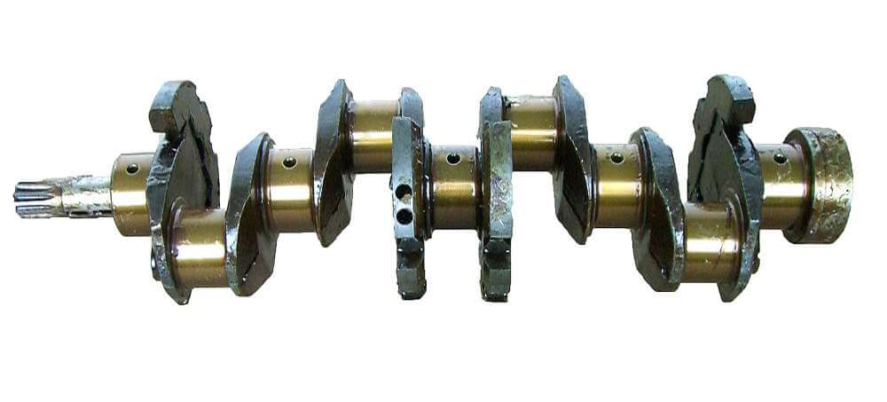
4 cylinder engine crankshaft
The main journals of the shaft are connected to the cheeks, which are one of the components of the crank. In the upper part of these cheeks there is a connecting rod journal.
The number of main and connecting rod journals depends on the number of cylinders, as well as their layout. In-line and V-twin engines place very large loads on the shaft, so the shaft must be mounted to the block to properly distribute this load.
To do this, there must be two main journals per shaft crank. But since the crank is placed between two journals, one of them will act as a support for the other crank. It follows from this that an in-line 4-cylinder engine has 4 cranks and 5 main journals on the shaft.
For V-twin engines the situation is somewhat different. In them, the cylinders are arranged in two rows at a certain angle. Therefore, one crank interacts with two connecting rods. Therefore, an 8-cylinder engine uses only 4 cranks, and again 5 main journals.
Reducing friction between the connecting rods and journals, as well as the block with main journals, is achieved through the use of liners - friction bearings, which are placed between the journal and connecting rod or block with a cover.
The shaft journals are lubricated under pressure. To supply oil, channels are used in the connecting rod and main journals, their covers, and liners.
During operation, forces arise that try to move the crankshaft in the longitudinal direction. To eliminate this, support half rings are used.
Diesel engines use counterweights that are attached to the crank cheeks to compensate for loads.
Flywheel
 A flange is made on one side of the shaft, to which a flywheel is attached, which performs several functions simultaneously. It is from the flywheel that rotation is transmitted. It has significant weight and dimensions, which makes it easier for the crankshaft to rotate after the flywheel spins. To start the engine, you need to create a significant force, so teeth are applied around the circumference of the flywheel, which are called the flywheel crown. Through this crown, the starter spins the crankshaft when starting the power plant. It is the flywheel that is attached to the mechanisms that use the rotation of the shaft to perform a useful action. In a car, this is the transmission that transmits rotation to the wheels.
To eliminate axial runout, the crankshaft and flywheel must be well balanced.
The other end of the crankshaft, opposite the flywheel flange, is often used to drive other mechanisms and engine systems: for example, an oil pump drive gear or a seat for a drive pulley can be placed there.
This is the basic diagram of the crankshaft. Nothing particularly new has been invented yet. All new developments are aimed so far only at reducing power losses as a result of friction between the elements of the cylinder head and the crankshaft.
They are also trying to reduce the load on the crankshaft by changing the angles of the cranks relative to each other, but there are no particularly significant results yet.
Autoleek