Li-ion battery charging modules based on the TP4056 controller have been described many times on mySKU. There are many uses - from remaking toys to household crafts. The popular module TP4056 with built-in protection based on DW01A is excellent in everything, only the lower voltage protection threshold is 2.5 ± 0.1 V, i.e. 2.4V in worst case. This is suitable for most modern batteries, because... they have a threshold of 2.5 V. What if you have a bag of batteries with a lower threshold of 2.75 V? You can spit and use them with such a module. It simply increases the risk that the battery will fail after being discharged. Or you can use an additional protection board, the lower voltage threshold of which corresponds to the batteries. This is exactly the kind of board I’ll talk about today.
I understand that most people are not interested in this topic, but let it be for the sake of history, because... sometimes the question comes up.
If you use batteries with built-in protection, then you do not need this board; you can safely use a “folk” module based on TP4056 without protection. If you use batteries without protection with a minimum voltage of 2.5 V, then you can safely use a “folk” module based on TP4056 with protection. 
I did not find any modules based on TP4056 with a threshold of 2.75 V on sale. I started looking for individual protection modules - there is a large selection, there are very cheap ones, but most of them are made on the same DW01A controller. The module from the review is the cheapest I could find. 275 rubles for 5 pieces.
The module is tiny, 39.5 x 4.5 x 2 mm. 

The contact pads are standard for protecting one cell: B+, B- for connecting the battery and P+, P- for connecting the charger and load.
Official specifications: 
The module is made on the basis of a controller. Version BM112-LFEA. Complies with technical specifications. The transistor is a double N-channel MOSFET transistor.
The connection diagram is simple: 
To activate the protection module, it is enough to supply power to P+, P-. Of course, it is not necessary to connect the TP4056; a battery with a protection module can quietly live its own life (like a regular battery with protection).
Practice test
This is not a laboratory test, errors can be large, but it will show the overall picture.I will use the converter as a regulated power supply, an EBD-USB tester and a TrustFire combat battery to test short-circuit protection. 
Minimum voltage: 
I reduce the voltage using a potentiometer. The protection is triggered at a voltage of 2.7 V. This is not the declared 2.88 V, but given the possible error, 2.75 V is suitable for batteries with a lower voltage threshold.
Maximum operating current: 
The maximum operating current is 3.6 A. If exceeded, protection is triggered. The response time depends on the heating of the transistor. If it is hot, it triggers immediately when setting 3.7 A. If it is cold, then after 30 seconds. At a current of 4 A, the protection is triggered almost immediately in any case. Those. There is no declared 4 A, but 3.6 A is also good.
Module temperature: 
After 5 minutes of operation at maximum current, the transistor heated up to 60 ºC, i.e. It is better not to adjoin the module close to the battery (without a gasket) during installation.
The protection resets after some time, or you can apply voltage from the memory to force a reset.
There is short circuit protection... one-time use :). I connected my combat TrustFire to the protection module and closed the P+, P- contacts via a multimeter. A current of 14 A flashed on the multimeter, and the “zilch” happened immediately. The transistor on the protection board burned out. At the same time, the protection board no longer passed current to the consumer, but essentially did not work anymore.
First of all, I built one module into the case for installing 18650 batteries (the USB connector is there just for convenience, without a converter). The kids and I usually use it for crafts using a mini drill. 
Conclusion
The protection modules are excellent. The declared characteristics almost correspond to the real ones. The only disappointment is the price, but I haven’t found a cheaper one for batteries with a threshold of 2.75 V. I'm planning to buy +77 Add to favorites I liked the review +49 +103Lithium ion batteries are the most efficient batteries available today. They are compact, have high energy consumption, and have no memory effect.
Despite all their advantages, they have one significant drawback: their operation and charging process must be carefully monitored. If a battery is discharged below a certain limit or overcharged, it quickly loses its properties, swells and even explodes. The same thing happens in case of overload and short circuits - heating, formation of gases and ultimately an explosion.
Some lithium-ion batteries are equipped with a safety valve to prevent the battery from exploding, but most high-power polymer batteries do not have such valves.
In other words, when operating lithium-ion batteries, a protection system is required.
Many people have probably noticed small circuit boards in mobile phone batteries, and this circuit board is the protection. It protects against deep discharge, overcharging and short circuits or current overloads.


The scheme of this protection is very simple, but and the board contains a couple of microcircuits with small things.

All processes are monitored by the DW01 chip. The second microcircuit is an assembly of two field-effect transistors.
The first transistor controls the discharge process, the second is responsible for charging the battery.During the discharge, the microcircuit monitors the voltage drop across the transitions of the field switches; if it reaches a critical value (150-200 mV), the microcircuit closes the transistors, disconnecting the battery from the load. The operation of the circuit is restored in less than a second after the load is removed.
The microcircuit monitors the voltage drop across the transistor transitions through the second pin.
Depending on the battery capacity, these controllers may differ radically in appearance, short circuit current and circuit topology, but their function is always the same - to protect the battery from overcharging, deep discharge and overcurrent. Many controllers also provide protection against overheating of the can; temperature control is carried out by a temperature sensor.
I have accumulated a lot of protection boards for mobile phone batteries, and just for one of my projects that involved a lithium-ion battery, I needed a protection system. The problem is that these boards are designed for a maximum current of 1 Ampere, but I needed a board with a current of at least 6-7 Amperes. Boards with the current required for my purposes cost less than half a dollar, but I couldn’t wait a month or two. Having examined the Chinese boards on Aliexpress, I realized that they are not much different from mine. The circuitry is the same, only the protection current is higher due to the parallel connection of power transistors.

When field-effect transistors are connected in parallel, the resistance of their channels will be significantly less, so the voltage drop across them will be less, and the protection response current will be greater. Parallel connection of switches will make it possible to switch large currents; the more switches, the greater the total switching current.


The scheme uses standard assemblies of two field workers in one housing. They are often used on battery protection boards for smartphones and more.
The 8205A assemblies have many analogues, just like the DW01 control chips.
After assembling the board, I tested it. The result was exactly what I needed for the project:
- The board charges the battery to a voltage of 4.2V and disconnects it from the charger;
- When the battery is discharged below 2.5V, the battery is disconnected from the load;
- At currents above 12-13 Amps, the battery is turned off.
Lithium-ion batteries have low self-discharge, but a battery supplemented with such a board will discharge faster than a battery without protection. The current consumption of the protection circuit is negligible, amounting to about 2.5 MICROamps.
More information about the operation of the protection board
(youtube)lXKELGFo79o (/youtube)
Assembling a powerful control board
(youtube)_w-AUCG4k_0 (/youtube)
Protection board for one LI-ION can http://ali.pub/28463y
Protection board for two cans
Progress is moving forward, and lithium batteries are increasingly replacing the traditionally used NiCd (nickel-cadmium) and NiMh (nickel-metal hydride) batteries.
With a comparable weight of one element, lithium has a higher capacity, in addition, the element voltage is three times higher - 3.6 V per element, instead of 1.2 V.
The cost of lithium batteries has begun to approach that of conventional alkaline batteries, their weight and size are much smaller, and besides, they can and should be charged. The manufacturer says they can withstand 300-600 cycles.
There are different sizes and choosing the right one is not difficult.
The self-discharge is so low that they sit for years and remain charged, i.e. The device remains operational when needed.
"C" stands for Capacity
A designation like “xC” is often found. This is simply a convenient designation of the charge or discharge current of the battery with shares of its capacity. Derived from the English word “Capacity” (capacity, capacity).When they talk about charging with a current of 2C, or 0.1C, they usually mean that the current should be (2 × battery capacity)/h or (0.1 × battery capacity)/h, respectively.
For example, a battery with a capacity of 720 mAh, for which the charge current is 0.5 C, must be charged with a current of 0.5 × 720 mAh / h = 360 mA, this also applies to discharge.
You can make a simple or not very simple charger yourself, depending on your experience and capabilities.
Circuit diagram of a simple LM317 charger

Rice. 5.
The application circuit provides fairly accurate voltage stabilization, which is set by potentiometer R2.
Current stabilization is not as critical as voltage stabilization, so it is enough to stabilize the current using a shunt resistor Rx and an NPN transistor (VT1).
The required charging current for a particular lithium-ion (Li-Ion) and lithium-polymer (Li-Pol) battery is selected by changing the Rx resistance.
The resistance Rx approximately corresponds to the following ratio: 0.95/Imax.
The value of resistor Rx indicated in the diagram corresponds to a current of 200 mA, this is an approximate value, it also depends on the transistor.
It is necessary to provide a radiator depending on the charging current and input voltage.
The input voltage must be at least 3 Volts higher than the battery voltage for normal operation of the stabilizer, which for one can is 7-9 V.
Circuit diagram of a simple charger on LTC4054

Rice. 6.
You can remove the LTC4054 charge controller from an old cell phone, for example, Samsung (C100, C110, X100, E700, E800, E820, P100, P510).

Rice. 7. This small 5-legged chip is labeled "LTH7" or "LTADY"
I won’t go into the smallest details of working with the microcircuit; everything is in the datasheet. I will describe only the most necessary features.
Charge current up to 800 mA.
The optimal supply voltage is from 4.3 to 6 Volts.
Charge indication.
Output short circuit protection.
Overheating protection (reduction of charge current at temperatures above 120°).
Does not charge the battery when its voltage is below 2.9 V.
The charge current is set by a resistor between the fifth terminal of the microcircuit and ground according to the formula
I=1000/R,
where I is the charge current in Amperes, R is the resistor resistance in Ohms.
Lithium battery low indicator
Here is a simple circuit that lights up an LED when the battery is low and its residual voltage is close to critical.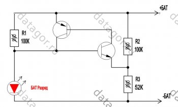
Rice. 8.
Any low-power transistors. The LED ignition voltage is selected by a divider from resistors R2 and R3. It is better to connect the circuit after the protection unit so that the LED does not drain the battery completely.
The nuance of durability
The manufacturer usually claims 300 cycles, but if you charge lithium just 0.1 Volt less, to 4.10 V, then the number of cycles increases to 600 or even more.Operation and Precautions
It is safe to say that lithium-polymer batteries are the most “delicate” batteries in existence, that is, they require mandatory compliance with several simple but mandatory rules, failure to comply with which can cause trouble.1. Charge to a voltage exceeding 4.20 Volts per jar is not allowed.
2. Do not short circuit the battery.
3. Discharge with currents that exceed the load capacity or heat the battery above 60°C is not allowed. 4. A discharge below a voltage of 3.00 Volts per jar is harmful.
5. Heating the battery above 60°C is harmful. 6. Depressurization of the battery is harmful.
7. Storage in a discharged state is harmful.
Failure to comply with the first three points leads to a fire, the rest - to complete or partial loss of capacity.
From the experience of many years of use, I can say that the capacity of batteries changes little, but the internal resistance increases and the battery begins to work less time at high current consumption - it seems that the capacity has dropped.
For this reason, I usually install a larger container, as the dimensions of the device allow, and even old cans that are ten years old work quite well.
For not very high currents, old cell phone batteries are suitable.

You can get a lot of perfectly working 18650 batteries out of an old laptop battery.
Where do I use lithium batteries?
I converted my screwdriver and electric screwdriver to lithium a long time ago. I don't use these tools regularly. Now, even after a year of non-use, they work without recharging!I put small batteries in children's toys, watches, etc., where 2-3 “button” cells were installed from the factory. Where exactly 3V is needed, I add one diode in series and it works just right.
I put them in LED flashlights.
Instead of the expensive and low-capacity Krona 9V, I installed 2 cans in the tester and forgot all the problems and extra costs.
In general, I put it wherever I can, instead of batteries.
Where do I buy lithium and related utilities
For sale. At the same link you will find charging modules and other useful items for DIYers.The Chinese usually lie about the capacity and it is less than what is written.

Honest Sanyo 18650
Protection of lithium-ion batteries (Li-ion). I think that many of you know that, for example, inside a mobile phone battery there is also a protection circuit (protection controller), which ensures that the battery (cell, bank, etc....) is not overcharged above a voltage of 4.2 V , or discharged less than 2...3 V. Also, the protection circuit saves from short circuits by disconnecting the can itself from the consumer at the moment of a short circuit. When the battery reaches the end of its service life, you can remove the protection controller board from it and throw away the battery itself. The protection board can be useful for repairing another battery, for protecting a can (which does not have protection circuits), or you can simply connect the board to the power supply and experiment with it.
I had many protection boards for batteries that had become unusable. But a search on the Internet for the markings of the microcircuits yielded nothing, as if the microcircuits were classified. On the Internet there was documentation only for assemblies of field-effect transistors, which are included in the protection boards. Let's look at the design of a typical lithium-ion battery protection circuit. Below is a protection controller board assembled on a controller chip designated VC87 and a transistor assembly 8814 ():
In the photo we see: 1 - protection controller (the heart of the entire circuit), 2 - assembly of two field-effect transistors (I will write about them below), 3 - resistor setting the protection operation current (for example during a short circuit), 4 - power supply capacitor, 5 - resistor (for powering the controller chip), 6 - thermistor (found on some boards to control the battery temperature).
Here is another version of the controller (there is no thermistor on this board), it is assembled on a chip with the designation G2JH, and on a transistor assembly 8205A ():

Two field-effect transistors are needed so that you can separately control the charging protection (Charge) and the discharge protection (Discharge) of the battery. There were almost always datasheets for transistors, but none for controller chips!! And the other day I suddenly came across an interesting datasheet for some kind of lithium-ion battery protection controller ().

And then, out of nowhere, a miracle appeared - after comparing the circuit from the datasheet with my protection boards, I realized: The circuits match, they are one and the same thing, clone chips! After reading the datasheet, you can use similar controllers in your homemade products, and by changing the value of the resistor, you can increase the permissible current that the controller can deliver before the protection is triggered.
There are two things that batteries really don't like: overcharging and overdischarging. And if the first problem is successfully solved by modern chargers (except for the simplest rectifiers), then with a discharge below a critical level things are worse - almost never battery-powered devices provide protection against overdischarge. An accidental discharge cannot be ruled out - when you simply forgot to turn off the device and it discharges, discharges... To solve this problem, a simple low-voltage circuit disconnect module is offered for self-assembly. This circuit is quite simple and can be applied to any lithium or lead-acid battery. Naturally, the shutdown threshold can be adjusted according to the battery.
Battery protection unit diagram
How it works. When the reset button is pressed, positive voltage is applied to the gate of the N-channel MOSFET power transistor.
If the voltage at the output of Zener diode U1 is higher than 2.5 volts, as determined by the voltage divider consisting of R4, R5 and R6, the cathode of U1 is connected to its anode, making it negative with respect to its emitter, R2 limits the base current to a safe value and provides sufficient current to operate U1. And transistor Q1 will keep the circuit open even when you release the reset button.
If the voltage at U1 drops below 2.5 volts, the zener diode turns off and pulls up the positive voltage at the emitter of R1, turning it off. Resistor R8 also turns off the field-effect transistor, resulting in the load being disconnected. Moreover, the load will not be turned on again until the reset button is pressed.
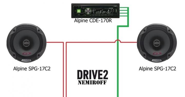
Most small FETs are rated for only +/- 20 volts at the gate source voltage, meaning the block circuit is suitable for no more than 12 volt devices: if higher operating voltages are required, additional circuit elements will need to be added to maintain safety fieldworker's work. An example of using such a circuit: a simple solar battery charge controller shown in the photo.

If a lower voltage than 9 volts (or higher than 15) is required, it will be necessary to recalculate the values of resistors R4 and R6 to change the adjustment range.
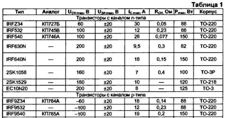
You can put almost any silicon PNP transistor with a rating of at least 30 volts and any N-channel MOSFET with a rated voltage of at least 30 volts and a current more than 3 times that which you are going to switch into the circuit. Feedthrough resistance of a fraction of Ohm. For the prototype, the F15N05 was used - 15 amps, 50 volts. For high currents, transistors IRFZ44 (50 A Max.) and PSMN2R7-30PL (100 A Max.) are suitable. You can also connect several field-effect transistors of the same type in parallel as needed.
This device should not remain connected to the battery for a long time, since it itself consumes several milliamps due to the LED and the current consumption of U1. When turned off, its current consumption is negligible.