Analog inputs of the Arduino board.
The Arduino UNO board contains 6 analog inputs for measuring voltage signals. It would be more correct to say that 6 outputs of the board can operate in the mode of both discrete outputs and analog inputs.
These pins are numbered 14 to 19. They are initially set up as analog inputs and can be referred to as A0-A5. At any time, they can be configured to the mode of discrete outputs.
pinMode(A3, OUTPUT); // setting the discrete output mode for A3
digitalWrite(A3, LOW); // setting output A3 low
To return to analog input mode:
pinMode(A3, INPUT); // setting the analog input mode for A3
Analog inputs and pull-up resistors.
Pull-up resistors are connected to the analog input pins, as well as to the digital pins. The inclusion of these resistors is performed by the command
digitalWrite(A3, HIGH); // turn on the pull-up resistor to input A3
The command must be applied to an output configured in input mode.
It must be remembered that the resistor can affect the level of the input analog signal. The current from the 5V power supply, through the pull-up resistor, will cause a voltage drop across the internal resistance of the signal source. So it is better to turn off the resistor.
Analog-to-digital converter board Arduino.
The actual voltage measurement at the inputs is performed by an analog-to-digital converter (ADC) with a switch for 6 channels. The ADC has a resolution of 10 bits, which corresponds to the converter output code 0...1023. The measurement error is not more than 2 units of the least significant digit.
To maintain maximum accuracy (10 digits), it is necessary that the internal resistance of the signal source does not exceed 10 kΩ. This requirement is especially important when using resistor dividers connected to the analog inputs of the board. The resistance of the divider resistors cannot be too large.
Analog input software functions.
int analogRead(port)
Reads the voltage value at the specified analog input. An input voltage ranging from 0 to the voltage reference level (often 5 V) is converted to a code from 0 to 1023.
With a reference voltage of 5 V, the resolution is 5 V / 1024 = 4.88 mV.
It takes about 100 µs to convert.
int inputCode; // input voltage code
float inputVoltage; // input voltage in V
inputCod=analogRead(A3); // read voltage at input A3
inputVoltage= ((float)inputCod * 5. / 1024.); // conversion code to voltage (V)
void analogReference(type)
Sets the reference voltage for the ADC. It defines the maximum analog input voltage that the ADC can correctly convert. The value of the reference voltage also determines the coefficient for converting the code into voltage:
Input voltage = ADC code * reference voltage / 1024.
The type argument can take the following values:
- DEFAULT - the reference voltage is equal to the controller supply voltage (5 V or 3.3 V). For Arduino UNO R3 - 5 V.
- INTERNAL - internal reference voltage 1.1 V for boards with ATmega168 and ATmega328 controllers, for ATmega8 - 2.56 V.
- INTERNAL1V1 - 1.1 V internal reference voltage for Arduino Mega controllers.
- INTERNAL2V56 - 2.56V internal reference voltage for Arduino Mega controllers.
- EXTERNAL – external reference voltage source, connected to the AREF input.
analogReference(INTERNAL); // reference voltage is 1.1 V
Two-channel voltmeter on Arduino.
As an example of using analog input functions, let's create a simple digital voltmeter project on Arduino. The device must measure voltages at two analog inputs of the board, and transfer the measured values to a computer via a serial port. Using the example of this project, I will show the principles of creating simple systems for measuring and collecting information.
We decide that the voltmeter should measure voltage in the range of at least 0 ... 20 V and develop a circuit for connecting the voltmeter inputs to the Arduino UNO board.
If we set the reference voltage to 5 V, then the analog inputs of the board will measure the voltage in the range of 0 ... 5 V. And we need at least 0 ... 20 V. So we need to use a voltage divider.
The voltage at the input and output of the divider are related by the relation:
Uout = (Uin / (R1 + R2)) * R2
Transmission ratio:
K = Uout / Uin = R2 / (R1 + R2)
We need a 1/4 gain (20V * 1/4 = 5V).
To maintain maximum accuracy (10 digits), it is necessary that the internal resistance of the signal source does not exceed 10 kΩ. Therefore, we choose the resistor R2 equal to 4.22 kOhm. We calculate the resistance of the resistor R1.
0.25 = 4.22 / (R1 + 4.22)
R1 \u003d 4.22 / 0.25 - 4.22 \u003d 12.66 kOhm
I found resistors with a resistance of 15 kOhm with the closest rating. With resistors R1 = 15 kΩ and R2 = 4.22:
5 / (4.22 / (15 + 4.22)) = 22.77 V.
The voltmeter circuit based on Arduino will look like this. 
Two voltage dividers are connected to analog inputs A0 and A1. Capacitors C1 and C2, together with the divider resistors, form low-pass filters that remove high-frequency noise from the signals.
I assembled this circuit on a breadboard.

I connected the first input of the voltmeter to a regulated power supply, and the second to the 3.3 V supply of the Arduino board. To control the voltage, I connected a voltmeter to the first input. It remains to write the program.
A program for measuring voltage using an Arduino board.
The algorithm is simple. Necessary:
- read the ADC code twice per second;
- convert it to voltage;
- send the measured values via the serial port to the computer;
- The Arduino IDE port monitor program displays the obtained voltage values on the computer screen.
I will give the sketch of the program in full.
// voltage measurement program
// on analog inputs A0 and A1
#include
measurement period time
#define R1 15. // resistor R1
#define R2 4.22 // resistor R2
float u1, u2; // measured voltages
void setup()(
Serial.begin(9600); //
MsTimer2::start(); // interrupt enable
}
void loop() (
// period 500 ms
if (timeCount >= MEASURE_PERIOD) (
timeCount=0;
//
// reading channel 2 code and converting to voltage
u2= ((float)analogRead(A1)) * 5. / 1024. / R2 * (R1 + R2);
// data transfer via serial port
Serial.print("U1 = "); Serial print(u1, 2);
Serial.print(" U2 = "); Serial.println(u2, 2);
}
}
// interrupt processing 1 ms
void timerInterupt() (
timeCount++;
}
Let me explain the line in which the ADC code is converted into voltage:
// reading channel 1 code and converting to voltage
u1= ((float)analogRead(A0)) * 5. / 1024. / R2 * (R1 + R2);
- The ADC code is read: analogRead(A0) .
- Explicitly converted to floating point format: (float) .
- Converted to voltage at the analog input: * 5. / 1024. The dot at the end of the numbers indicates that this is a floating point number.
- The divider ratio is taken into account: / R2 * (R1 + R2) .
Let's load the program into the board, start the serial port monitor.

Two running bars show the values of the measured voltages. Everything is working.
Measuring the average value of the signal.
Let's connect the first channel of our voltmeter to a voltage source with a high level of ripple. We will see such a picture on the monitor.

The voltage values of the first channel on the monitor screen are twitching and jumping all the time. And the readings of the control voltmeter are quite stable. This is because the reference voltmeter measures the average value of the signal, while the Arduino board reads individual samples every 500ms. Naturally, the moment of reading the ADC falls into different points of the signal. And at a high level of pulsations, the amplitude at these points is different.
In addition, if the signal is read in separate rare samples, then any impulse noise can introduce a significant error into the measurement.
The solution is to take several frequent samples and average the measured value. For this:
- in the interrupt handler, we read the ADC code and sum it with the previous samples;
- count the averaging time (the number of averaging samples);
- when the specified number of samples is reached, we save the total value of the ADC codes;
- to obtain the average value, we divide the sum of the ADC codes by the number of averaging samples.
A task from a 8th grade math textbook. Here is a sketch of the program, a two-channel average value voltmeter.
// medium voltage measurement program
// on analog inputs A0 and A1
#include
#define MEASURE_PERIOD 500 // measurement period time
#define R1 15. // resistor R1
#define R2 4.22 // resistor R2
int timeCount; // time counter
long sumU1, sumU2; // variables for summing ADC codes
long availabilityU1, availabilityU2; // sum of ADC codes (average * 500)
boolean flagReady; // sign of readiness of measurement data
void setup()(
Serial.begin(9600); // initialize the port, speed 9600
MsTimer2::set(1, timerInterupt); // timer interrupts, period 1 ms
MsTimer2::start(); // interrupt enable
}
void loop() (
if (flagReady == true) (
flagReady=false;
// conversion to voltage and transfer to a computer
Serial.print("U1 = ");
Serial.print((float)avarageU1 / 500. * 5. / 1024. / R2 * (R1 + R2), 2);
Serial.print(" U2 = ");
Serial.println((float)avarageU2 / 500. * 5. / 1024. / R2 * (R1 + R2), 2);
}
}
// interrupt processing 1 ms
void timerInterupt() (
timeCount++; // +1 averaging sample counter
sumU1+= analogRead(A0); // summation of ADC codes
sumU2+= analogRead(A1); // summation of ADC codes
// checking the number of averaging samples
if (timeCount >= MEASURE_PERIOD) (
timeCount=0;
availabilityU1=sumU1; // mean value overload
avarageU2=sumU2; // mean value overload
sumU1= 0;
sumU2=0;
flagReady=true; // sign measurement result is ready
}
}
/500, the number of samples, was added to the formula for converting the ADC code into voltage. Load, run the port monitor (Cntr + Shift + M).

Now, even with a significant level of ripple, the readings change by hundredths. This is only because the voltage is not stabilized.
The number of samples should be chosen taking into account:
- the number of samples determines the measurement time;
- the larger the number of samples, the smaller the influence of interference will be.
The main source of interference in analog signals is the 50 Hz network. Therefore, it is desirable to choose an averaging time that is a multiple of 10 ms - the half-cycle time of the network with a frequency of 50 Hz.
Optimization of calculations.
Floating point calculations simply devour the resources of an 8-bit microcontroller. Any floating point operation requires mantissa denormalization, fixed point operation, mantissa normalization, exponent correction... And all operations with 32 bit numbers. Therefore, it is necessary to minimize the use of floating point calculations. I will tell you how to do this in the next lessons, but let's at least optimize our calculations. The effect will be significant.
In our program, the conversion of the ADC code into voltage is written as follows:
(float)avarageU1 / 500. * 5. / 1024. / R2 * (R1 + R2)
How many calculations are there, and all are floating point. But most of the calculations are operations with constants. Line part:
/ 500. * 5. / 1024. / R2 * (R1 + R2)
(float)avarageU1 * 0.00004447756
Smart compilers themselves recognize calculations with constants and calculate them at compile time. I had a question how smart Andruino's compiler is. Decided to check.
I wrote a short program. It performs a cycle of 10,000 passes and then transmits to the computer the execution time of these 10,000 cycles. Those. it allows you to see the execution time of the operations placed in the loop body.
// calculation optimization check
int x= 876;
float y;
unsigned int count;
unsigned long timeCurrent, timePrev;
void setup()(
Serial.begin(9600);
}
void loop() (
count++;
// y= (float)x / 500. * 5. / 1024. / 4.22 * (15. + 4.22);
// y= (float)x * 0.00004447756 ;
if (count >= 10000) (
count=0;
timeCurrent=millis();
Serial.println(timeCurrent - timePrev);
timePrev= timeCurrent;
}
}
In the first variant, when floating-point operations are commented out and not executed in the loop, the program gave a result of 34 ms.

Those. 10,000 empty cycles are completed in 34ms.
Then I opened the line:
y= (float)x / 500. * 5. / 1024. / 4.22 * (15. + 4.22);
repeats our calculations. Result 10,000 passes in 922 ms or
(922 - 34) / 10,000 = 88.8 µs.
Those. this line of floating point calculations takes 89 µs to complete. I thought there would be more.
Now I closed this line with a comment and opened the next one, multiplied by a pre-calculated constant:
y= (float)x * 0.00004447756 ;
Result 10,000 passes in 166 ms or
(166 - 34) / 10,000 = 13.2 µs.
Amazing result. We saved 75.6 µs per line. Completed it almost 7 times faster. We have 2 such lines. But there can be much more of them in the program.
Conclusion - calculations with constants must be done by yourself on a calculator and used in programs as ready-made coefficients. The Arduino compiler will not calculate them at the compilation stage. In our case, we should do this:
#define ADC_U_COEFF 0.00004447756 // ADC code to voltage conversion factor
Serial.print((float)avarageU1 * ADC_U_COEFF, 2);
The optimal speed option is to transfer the ADC code to the computer, and with it all floating-point calculations. In this case, a specialized program should receive data on the computer. The port monitor from the Arduino IDE will not work.
I will talk about other ways to optimize Arduino programs in future lessons as needed. But without solving this issue, it is impossible to develop complex programs on an 8-bit microcontroller.
Another lesson appeared on the site () dedicated to measuring analog signals. It deals with the operation of the ADC in the background.
In the next lesson, we will learn how to work with the internal EEPROM, let's talk about data integrity control.
Category: . You can bookmark.Hey Habr! Today I want to continue the topic of "crossing" arduino and android. In a previous publication, I talked about a bluetooth machine, and today we will talk about a DIY bluetooth voltmeter. Another such device can be called a smart voltmeter, "smart" voltmeter or just a smart voltmeter, without quotes. The last name is incorrect from the point of view of the grammar of the Russian language, however, it is often found in the media. Voting on this topic will be at the end of the article, and I propose to start by demonstrating the operation of the device in order to understand what the article will be about.
Disclaimer: the article is intended for the average arduino fan who is usually not familiar with android programming, therefore, as in the previous article, we will make a smartphone application using the App Inventor 2 visual development environment for android applications.
To make a DIY bluetooth voltmeter, we need to write two relatively independent programs: an arduino sketch and an android application. Let's start with a sketch.
To begin with, you should know that there are three main options for measuring voltage using arduino, regardless of where you want to display information: to a com-port, to a screen connected to arduino, or to a smartphone.
First case: voltage measurements up to 5 volts. One or two lines of code are enough here, and the voltage is applied directly to pin A0:
int value = analogRead(0);// read readings from A0
voltage = (value / 1023.0) * 5; // true only if Vcc = 5.0 volts
Second case: a voltage divider is used to measure voltages over 5 volts. The scheme is very simple, the code too.
Sketch
int analogInput = A0;
float value = 0.0;
float voltage = 0.0;
float R1 = 100000.0; //Battery Vin -> 100K -> A0
float R2 = 10000.0; //Battery Gnd -> Arduino Gnd and Arduino Gnd -> 10K -> A0
int value = 0;
Void setup() (
Serial.begin(9600);
pinMode(analogInput, INPUT);
}
void loop() (
value = analogRead(analogInput);
val = (value * 4.7) / 1024.0;
voltage = val / (R2/(R1+R2));
Serial println(voltage);
delay(500);
}
Arduino Uno
bluetooth module
Third case. When you need to get more accurate about the voltage, as a reference voltage, you need to use not the supply voltage, which can change slightly when powered from the battery, for example, but the voltage of the internal arduino stabilizer is 1.1 volts. Here the circuit is the same, but the code is slightly longer. I will not analyze this option in detail, since it is already well described in thematic articles, but the second method is quite enough for me, since my power supply is stable, from the laptop's usb port.
So we figured out the voltage measurement, now let's move on to the second half of the project: creating an android application. We will make the application directly from the browser in the App Inventor 2 visual development environment for android applications. We go to the site appinventor.mit.edu/explore , log in using a Google account, press the create, new project button, and by simply dragging and dropping elements we create something like this design:

I made the graphics very simple, if someone wants more interesting graphics, let me remind you that for this you need to use .png files with a transparent background instead of .jpeg files.
Now go to the Blocks tab and create the application logic there like this:

If everything worked out, you can click the Build button and save .apk to my computer, and then download and install the application on your smartphone, although there are other ways to upload the application. here it's more convenient for someone. As a result, I got this application:


I understand that few people use the App Inventor 2 visual development environment for android applications in their projects, so many questions may arise about working in it. To remove some of these questions, I made a detailed video on how to make such an application from scratch (you need to go to YouTube to view it):
P.S. A collection of over 100 arduino tutorials for beginners and pros
A useful scheme is presented for those who like to experiment with Arduino. This is a simple digital voltmeter that can reliably measure DC voltage in the range of 0 - 30V. The Arduino board, as usual, can be powered by a 9V battery.
As you probably know, Arduino analog inputs can be used to measure DC voltage in the range of 0 - 5V and this range can be increased,
using two resistors as a voltage divider. The divider will reduce the measured voltage to the level of Arduino analog inputs. And then the program will calculate the real value of the voltage.
The analog sensor on the Arduino board detects the presence of voltage at the analog input and converts it into a digital form for further processing by the microcontroller. In the figure, voltage is applied to the analog input (A0) through a simple voltage divider consisting of resistors R1 (100kΩ) and R2 (10kΩ).
With these divisor values, the Arduino board can be supplied with voltage from 0 to
55V. At the input A0 we have the measured voltage divided by 11, i.e. 55V / 11=5V. In other words, when measuring 55V at the Arduino input, we have the maximum allowable value of 5V. In practice, it is better to write the range “0 - 30V” on this voltmeter in order to remain
Safety margin!

Notes
If the display readings do not match the readings of an industrial (laboratory) voltmeter, then it is necessary to measure the resistance R1 and R2 with an accurate instrument and insert these values instead of R1=100000.0 and R2=10000.0 in the program code. Then you should measure the real voltage between the 5V and “Ground” terminals of the Arduino board with a laboratory voltmeter. The result will be a value less than 5V, for example, it turned out 4.95V. This real value should be inserted in a line of code
vout = (value * 5.0) / 1024.0 instead of 5.0.
Also, try to use precision resistors with a tolerance of 1%.
Resistors R1 and R2 provide some protection against high input voltages. However, be aware that any voltages above 55V can damage the Arduino board. In addition, this design does not provide other types of protection (from power surges, from reverse polarity or overvoltage).

Digital Voltmeter Program
/*
DC Voltmeter
An Arduino DVM based on voltage divider concept
T.K.Hareendran
*/
#include
LiquidCrystal lcd(7, 8, 9, 10, 11, 12);
int analogInput = 0;
float vout = 0.0;
float vin = 0.0;
float R1 = 100000.0; // resistance of R1 (100K) -see text!
float R2 = 10000.0; // resistance of R2 (10K) - see text!
int value = 0;
void setup()(
pinMode(analogInput, INPUT);
lcd.begin(16, 2);
lcd.print("DC VOLTMETER");
}
void loop()(
// read the value at analog input
value = analogRead(analogInput);
vout = (value * 5.0) / 1024.0; // see text
vin = vout / (R2/(R1+R2));
if (vin<0.09) {
vin=0.0;//statement to quash undesired reading !
}
lcd.setCursor(0, 1);
lcd.print("INPUT V=");
lcd print(vin);
delay(500);
}
Schematic diagram of the Arduino voltmeter

List of components
Arduino Uno Board
100 kΩ resistor
10 kΩ resistor
100 ohm resistor
10kΩ Trimmer Resistor
LCD display 16×2 (Hitachi HD44780)
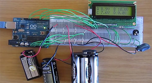
Four-channel "Arduino-voltmeter" can measure four independent DC voltages in the range from 0 to 50V. Analog channels A2 to A5 on the Arduino Uno are used to measure four different voltages. The measured voltage values are displayed on a 16-character, two-line LCD display.
Voltages are displayed as a value with one decimal place, e.g. 5.3V, 12.8V, etc.
The video below shows an Arduino-based voltmeter that measures the voltage of four batteries at different voltage levels.
The principle of operation of the voltmeter
Each channel of the Arduino-based voltmeter has a pair of resistors that form a voltage divider. The voltage divider reduces the input voltage to a level that can be measured by the Arduino. The running Arduino code calculates the actual voltage value and displays the result on the LCD.
Before starting to assemble the circuit, make sure that your LCD has the same number of pins as the display shown in the diagram. If connected incorrectly, the LCD display may be damaged.
This tutorial shows you how to connect an LCD display to an Arduino Uno board.
Voltage is measured between points A, B, C or D and ground or 0V. Remember to adjust the contrast level with the potentiometer so that the LCD display is visible.
Resistor R1 provides current limiting for the optional backlight and allows it to be permanently on.
Arduino voltmeter sketch
The sum and voltage variables are combined into an array, which allows you to store readings from four analog channels.
Calibration
The calibration process is described in detail in the article Measuring DC voltage using Arduino, but in our case we need to calculate the division factor of 4 voltage dividers.
The calibration values can be easily changed at the top of the code:
// voltage divider calibration values #define DIV_1 11.1346 #define DIV_2 11.1969 #define DIV_3 11.0718 #define DIV_4 11.0718 // ADC reference voltage / calibration value #define V_REF 4.991
Reference voltage calibration
Measure the 5V voltage and change the values of the V_REF constant according to the measured value. Measure the voltage in the circuit with the LCD connected and with the sketch running, as the voltage may change when the LCD is connected. For example, with the circuit connected, the voltage value from 5.015V with the LCD off can drop to 4.991V with the LCD connected on the same hardware.
Voltage divider calibration
Change the voltage divider values for each voltage divider from DIV_1 to DIV_4 at the top of the sketch. DIV_1 to DIV_4 correspond to analog pins A2 to A5.
List of radio elements
| Designation | Type | Denomination | Quantity | Note | Shop | My notepad |
|---|---|---|---|---|---|---|
| Arduino board | Arduino Uno | 1 | To notepad | |||
| R1 | Resistor | 47 ohm | 1 | To notepad | ||
| R2, R4, R6, R8 | Resistor | 1 MΩ | 4 | To notepad | ||
| R3, R5, R7, R9 | Resistor | 100 kOhm | 4 | To notepad | ||
| RV1 | Trimmer resistor | 10 kOhm | 1 | To notepad | ||
| LCD | LCD display | 16x2 HD44780 | 1 |
This article provides an interesting scheme for lovers of experiments and Arduino. It presents a simple digital voltmeter that can safely measure DC voltage in the range of 0 to 30V. The Arduino board itself can be powered from a standard 9V supply.
As you know, using the Arduino analog input, you can measure voltage from 0 to 5 V (with a standard reference voltage of 5 V). But this range can be extended by using a voltage divider.
The divider lowers the measured voltage to an acceptable level for the analog input. The specially written code then calculates the actual voltage.

The analog sensor in the Arduino detects the voltage at the analog input and converts it into a digital format that is accepted by the microcontroller. To the analog input A0 we connect a voltage divider formed by the resistances R1 (100K) and R2 (10K). With these resistance values, up to 55V can be supplied to the Arduino, since the division factor in this case is 11, so 55V/11=5V. In order to be sure of the safety of measurements for the board, it is better to measure the voltage in the range from 0 to 30 V.

If the display does not match the calibrated voltmeter, use a precision digital multimeter to find the exact R1 and R2 values. In this case, in the code, you will need to replace R1=100000.0 and R2=10000.0 with your own values. Then it is worth checking the power by measuring the voltage on the board between 5V and GND. The voltage can be 4.95 V. Then in the code vout = (value * 5.0) / 1024.0 you need to replace 5.0 with 4.95. It is advisable to use precision resistors with an error of no more than 1%. Remember that voltages above 55V can damage the Arduino board!
#include

Used elements:
Arduino Uno Board
Resistor 100 kΩ
Resistor 10 kΩ
100 ohm resistor
Potentiometer 10 kΩ
LCD display 16×2