All electronic engineers involved in the design of power supply devices sooner or later face the problem of the lack of a load equivalent or the functional limitations of the existing loads, as well as their dimensions. Fortunately, the appearance of cheap and powerful field-effect transistors on the Russian market has somewhat corrected the situation.
Amateur designs of electronic loads based on field-effect transistors began to appear, more suitable for use as electronic resistance than their bipolar counterparts: better temperature stability, almost zero channel resistance in the open state, low control currents - the main advantages that determine the preference for their use as regulating component in powerful devices. Moreover, a wide variety of offers have appeared from device manufacturers, whose price lists are replete with a wide variety of models of electronic loads. But, since manufacturers focus their very complex and multifunctional products called “electronic loads” mainly on production, the prices for these products are so high that only a very wealthy person can afford the purchase. True, it is not entirely clear why a wealthy person needs an electronic load.
I have not noticed any commercially manufactured EN aimed at the amateur engineering sector. This means that you will have to do everything yourself again. Eh... Let's begin.
Advantages of Electronic Load Equivalent
Why, in principle, are electronic load equivalents preferable to traditional means (powerful resistors, incandescent lamps, thermal heaters and other devices) often used by designers when setting up various power devices?Citizens of the portal who are involved in the design and repair of power supplies undoubtedly know the answer to this question. Personally, I see two factors that are sufficient to have an electronic load in your “laboratory”: small dimensions, the ability to control the load power within large limits using simple means (the same way we regulate the sound volume or the output voltage of the power supply - with a regular variable resistor and not by powerful switch contacts, rheostat motor, etc.).
In addition, the “actions” of the electronic load can be easily automated, thus making it easier and more sophisticated to test a power device using an electronic load. At the same time, of course, the engineer’s eyes and hands are freed, and the work becomes more productive. But the delights of all possible bells and whistles and perfections are not in this article, and, perhaps, from another author. In the meantime, let's talk about just one more type of electronic load - pulsed.

Regarding resistor R16. When a current of 10A passes through it, the power dissipated by the resistor will be 5W (with the resistance indicated on the diagram). In the actual design, a resistor with a resistance of 0.1 Ohm is used (the required value was not found) and the power dissipated in its body at the same current will be 10 W. In this case, the temperature of the resistor is much higher than the temperature of the EN keys, which (when using the radiator shown in the photo) do not heat up much. Therefore, it is better to install the temperature sensor on resistor R16 (or in the immediate vicinity), and not on the radiator with EN keys.
A few more photos


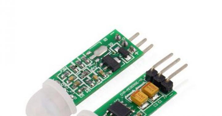
From time to time, radio amateurs need an electronic load. What is an electronic load? Well, to put it simply, this is a device that allows you to load a power supply (or other source) with a stable current that is naturally regulated. The respected Kirich has already written about this, but I decided to try a “proprietary” device in practice, stuffing it into some kind of case and attaching an indication device to it. As you can see, they combine perfectly according to the stated parameters.
So, the load is 59x55mm, a pair of 6.5mm terminals are included (very tight, and even with a latch - you can’t just remove it, you need to press a special tongue. Excellent terminals), a 3-wire cable with a connector for connecting a potentiometer, a two-wire cable with a connector for connecting power, an M3 screw for screwing the transistor to the radiator. 
The scarf is beautiful, the edges are milled, the soldering is smooth, the flux is washed off. 
The board has two power connectors for connecting the load itself, connectors for connecting a potentiometer (3-pin), power (2-pin), fan (3-pin) and three contacts for connecting a device. Here I would like to draw your attention to the fact that usually The black thin wire from the measuring device will not be used! In particular, in my case, with the device described above (see link to the review), there is NO NEED to connect a thin black wire, because the power supply for both the load and the device comes from the same power supply. 
Power element - transistor (200V, 30A) 
Well, among the microcircuits on the board there is a comparator LM393, an op-amp LM258 and an adjustable zener diode TL431. 
Found on the Internet: 
To be honest, I haven’t thoroughly rechecked the entire circuit, but a quick comparison of the circuit diagram with the board showed that everything seems to fit together.
Actually, there’s nothing more to say about the load itself. The scheme is quite simple and generally speaking cannot fail. And the interest in this case is rather its operation under load as part of the finished device, in particular the temperature of the radiator.
I thought for a long time about what to make the body out of. there was an idea to bend it from stainless steel, glue it from plastic... And then I thought - this is it, the most accessible and repeatable solution - a “push-button station” KP-102, with two buttons. I found the radiator in a box, the fan in the same place, bought the terminals and switch offline, and dug out bananas and a power socket from something old in the attic;)

Looking ahead, I will say that I screwed up, and the transformer that I used (complete with a rectifier bridge, of course) did not support this device due to the high current consumed by the fan. Alas. I'll order it, it should fit just right in size. As an option, you can use an external 12V power supply, of which there are also plenty on the bang and in the arsenal of any radio amateur. It is highly undesirable to power the load from the power supply under study, not to mention the voltage range.
In addition, we will need a 10 kOhm potentiometer to adjust the current. I recommend installing multi-turn potentiometers, for example or. There are nuances here and there. the first type - for 10 turns, the second for 5. The second type has a very thin shaft, about 4mm, it seems, and standard handles do not fit - I pulled two layers of heat shrink. the first type has a thicker shaft, but IMHO it also doesn’t reach standard sizes, so problems are possible - however, I didn’t hold them in my hands, so I can’t say 100% sure. Well, as you can see, the diameter/length is noticeably different, so you need to estimate according to location. I had potentials of the second type in stock, so I didn’t worry about this, although I should have bought the first ones for the collection. The potentiometer needs a handle - for aesthetics and convenience. It seems like handles should be suitable for potentiometers of the first type; in any case, they have a fixing screw and will hold normally on a smooth shaft. I used what was available, stretching a couple of layers of heat shrink and dripping with superglue to fix the heat shrink to the shaft. This is a proven method - I’ve been using it for the power supply for a couple of years now, so far everything is working.

Then there were the torments of the layout, which showed that in fact the only possible solution is what I will give below. Unfortunately, this solution requires trimming the case, because due to the stiffening ribs the board does not fit in, and the switch and regulator do not fit in because I tried to place them in the center of the recesses on the case, but they ended up resting against a thick wall inside. If I knew, I would turn the front panel over.
So, we mark and make holes for the network connector, transistor and radiator on the back wall: 
Now the front panel. The hole for the device is simple (although, as I wrote in the previous review, its latches are stupid, and I, out of harm’s way, preferred to first snap the body of the device into the body of the device, and then snap the insides of the device into it). The holes for the switch and regulator are also relatively simple, although we had to use a milling machine to select the grooves on the walls. But how to arrange the sockets in order to “bypass” the hole on the front panel is a challenge. But I glued a piece of black plastic and drilled holes directly into it. It turned out beautiful and neat.

Now a nuance. We have a temperature sensor in the device. But why measure the temperature in the case if you can lean it against the radiator? This is much more useful information! And since the device is disassembled anyway, nothing prevents you from unsoldering the temperature sensor and extending the wires. 
To press the sensor to the radiator, I glued a piece of plastic to the body in such a way that by loosening the radiator mounting screws, I could slide the temperature sensor under the plastic, and by tightening these screws, I could securely fix it there. The hole around the transistor was made several mm larger in advance.

Well, let’s cram this whole “explosion at a pasta factory” into the case: 

Result: 

Checking the radiator temperature: 

As we can see, at about 55W, after 20 minutes, the temperature of the radiator in the immediate vicinity of the power transistor stabilized at 58 degrees.
This is the outside temperature of the radiator itself: 

Here, I repeat, there are nuances: at the time of testing, the device was operating from a weak transformer and not only did the voltage drop to 9 volts under load (that is, with normal power supply the cooling will be SIGNIFICANTLY better), but also due to poor quality power supply the current cannot really be stabilized It was possible, so it looks a little different in different photos.
When powered from the crown and, accordingly, with the fan turned off, we have this: 
The wires from the power supply are thin, so the voltage drop here is quite significant, and if you wish, you can further reduce the number of transition resistances by soldering wherever possible and removing the terminals. I’m quite happy with this accuracy - however, we talked about accuracy in the last review. ;)
Conclusions: a completely working thing that allows you to save time on developing your own solution. It probably shouldn’t be taken as a “serious” and “professional” load, but IMHO it’s a great thing for beginners, or when it’s rarely needed.
Among the advantages, I can note the good quality of workmanship, but perhaps there is only one disadvantage - the lack of a potentiometer and radiator in the kit, and this must be kept in mind - the device will have to be completed in order for it to start working. The second disadvantage is the lack of thermal control of the fan. Despite the fact that the “unnecessary” half of the comparator is there. But this had to be included at the stage of development and manufacturing of the board, because if you hang the thermostat “from above”, then it would be more reasonable to assemble it on a separate board;)
According to my finished design, there are also nuances, in particular, it will be necessary to change the power supply, and generally speaking it would be nice to install some kind of fuse. But a fuse is extra contacts and extra resistance in the circuit, so I’m not completely sure yet. You can also move the shunt from the device onto the board and use it for both the device and the load electronics, removing the “extra” shunt from the circuit.
There are undoubtedly “more” electronic loads that cost comparable. For example . The difference between the one under review is in the declared input voltage, up to 100V, while most loads are designed to operate up to 30V. Well, in this case we have a modular design, which personally suits me very much. Tired of the device? They made it more precise or larger, or something else. Not satisfied with the power? Changed the transistor or radiator, etc.
In a word, I’m quite pleased with the result (well, just screw on a different power supply - but I’m a fool myself, and you’ve been warned), and I highly recommend purchasing it.
The product was provided for writing a review by the store. The review was published in accordance with clause 18 of the Site Rules.
I'm planning to buy +36 Add to favorites I liked the review +43 +72 November 8, 2017, 02:47I have already written at least three reviews of electronic loads, both completely homemade and assembled from a “designer”, as well as factory-made ones. In this case, both options belong rather to the class of “designers”, since they are not a functionally complete product, although they can work on their own, they require at least a power supply.
I saw them almost a year ago, became interested, and so decided to buy them, and at the same time check how to “buy them on Tao”.
In general, anyone who is interested in this topic will find a lot of interesting things for themselves.
Partly the prerequisite for buying was the difficulty of testing powerful power supplies, when my 300-400 Watts were not enough, partly the expansion of my horizons, and not the least on the list was an attempt to buy on Taobao, because there are some very interesting things there.
There were no problems with the purchase, and as a result, after some time I received a rather large parcel. Here I made a small mistake, delivery is quite expensive, and my pieces of iron are quite heavy.
Everything was packaged just fine, but this was also a small minus, since the more packaging material, the higher the delivery cost :(
In the second photo you see not two products, but one. In this case, on the right is one of the loads, and on the left is what it was packed in.
The second load was packed even better, but in this case it was the seller’s packaging, such a soft box.
No, everything is great, the intermediary not only packed it well, but also sent a letter before that, saying, dear Kirich, we received two incomprehensible pieces of iron, but we have no idea how to check them, we don’t even know what it is...
To which I replied, calm down, don’t panic, compare with the photo in the store, if it’s similar, then send it :) 
In general, I got to the bottom of my order and in the end there were only two electronic loads on the table. 
I’ll show you the “stupid” one first, i.e. without the ability to connect to a computer, just a load.
Claimed power - up to 300 Watt
Voltage - up to 150 Volts
Current - up to 40 Amperes
Modes - CC\CV
There were many different options in the assortment, which conventionally differ in voltage 150/60 Volts, as well as current 10/20/30/40 Amps, as well as the adjustment design - a connector on the board, a tuning resistor on the board or an external variable resistor. 
I immediately chose the most sophisticated option and at the same time the most powerful, i.e. 150 Volts, 40 Amps, 300 Watts with external resistor.
As you can see, the design consists of essentially two identical modules connected together. There is also an option with a power of 150 Watt, consisting of one module. 
An external resistor means a regular variable resistor on a small strip. I’ll jump ahead a little, there’s no point in ordering this way, for convenient control you need to either order a load with a 60 Volt range, or even better, install a multi-turn resistor. 
The design of the cooling system (actually the heaviest part) consists of two fans and a special aluminum radiator through which air is blown.
5 points for the design, where can you get hold of such an aluminum profile? It’s even better if the size is not 50x50mm, but for example 80x80, or at least 60x60. 
A pair of quite powerful, but also very noisy fans, covered with protective grilles. At first I thought, here are the economists, they put only two screws on the grille, then it turned out that there was simply nowhere to screw in the second pair of screws. No, they are still economists :) 
Two control boards are connected together, although it would be more correct to say that they are not disconnected, since this is how they usually go during manufacturing.
Wiring is stretched from one board to another and the idea is clearly visible when one board is made the master, and the second the slave. 
Most of the connectors are missing, but I’ll try to explain what’s what.
Ref - regulation by external voltage 0-5 Volts.
Potentiometer - external variable resistor, the middle contact is connected to the same Ref, i.e. changes the voltage in the range of 0-5 Volts.
Fan - connecting a fan, the wires are simply soldered without any connectors.
Con 1, a connector is soldered into the left board - power supply 12-15 Volts.
There is also room for a 74HC connector. In general, this is usually a designation for a series of logical chips, but I don’t know what in this case. One contact goes to ground, four to the microcontroller.
Con 4 - temperature sensor. 
The other end of the board has power connectors for connecting the load, as well as:
Con 2 is essentially in series with the power connector Vin, most likely a fuse should be placed there, in fact there is some kind of plate soldered there. Another option is to connect an ammeter, but the connector is kind of flimsy for a current of 20 Amps.
Con 3 - ground, +12 Volts and input voltage Vin are connected to this connector. You can connect a voltmeter here
Fan 2 - Connection of a second fan (working for blowing), connected in parallel to the first. 
Four IRFP460A field-effect transistors act as the actual load. It turns out 75 watts per TO-247 case, in my opinion this is a lot, a lot, the power is exceeded by at least 1.5 times. This is due to the fact that field-effect transistors work much harder in linear mode. Actually, that’s why in my homemade one, for a power of 400 Watts, 8 transistors are installed, 50 Watts per case, and even that is a bit much.
But I cannot help but note that the transistors are connected correctly; each transistor has not only its own shunt, but also its own operational amplifier. I used exactly this solution in my version. 
The board is screwed with four screws through the stands, the transistors have their own fasteners, and not only thermal paste was not forgotten, but also the correct screws with a flat washer + Grover washer.
When I took it apart, I subconsciously expected that the radiators would fall apart, but no, everything worked out, the radiators seemed to be glued together.
But the racks could have been tightened even more tightly... 
From below you can more clearly see how the boards are connected to each other. By the way, for a more correct connection of power wires, you need to connect the plus to one board, and the minus to the other. 
If there are no particular questions about the connection of the power connectors, then the wires in varnish insulation for connecting the power supply to the modules look somehow completely wrong. I understand that they are simply hidden there, but one wire was touching the stand and over time, due to vibration, it would scrape the insulation. You will of course ask where the vibration comes from. This is how two fairly powerful fans work, and such wires don’t need more. 
One of the “halves” is closer. 

1. The power input is protected not only by a 1 Ampere fuse, but also by a diode that protects against polarity reversal. But in addition, they installed a bunch of capacitors along the power supply circuit, it’s even surprising :)
2. Although the load is “stupid”, it still contains a microcontroller. In this case, it controls operating modes, overpower protection, and the fan.
3, 4. Three LM321 operational amplifiers. A pair serves current sensors and transistor control, and one (as far as I understand) is CV mode.
Speaking of fan control. Made very thoughtfully. If the load is cold, the fan is turned off. It turns on stepwise when the power exceeds 20-30 watts per module, gradually increasing the blowing power.
If you turn off the load when the radiators are cold, the fans turn off immediately. But if you warm it up first, they will turn off only when the temperature drops to about 35 degrees.
Those. The fans are controlled in stages depending on power and temperature. 
A ceramic capacitor is installed parallel to the input and power terminals. My old one also has a capacitor, but it has a noticeably larger capacity, so sometimes it sparks a little when power is applied to the input. 
The less powerful and more “smart” load had noticeably fewer choices, 60/150 Volts and 5/10/20 Amps. And again I chose the most powerful and high-voltage option, and in this case this may have been a mistake.
Below is the SPI connector, as I understand it, it is more needed to connect the programmer.
Even lower is a long row of contacts; microcontroller ports and power supply are located here.
But I don’t understand what SWIM is, a little to the right and higher. It looks like some kind of jumper is placed there, the middle pin goes to the microcontroller, the outer pins go to ground and power. Those. In this way, you can set three signals - 1, 0 and Z. I tried all the options in the process, but did not notice any difference. 
If in the previous load everything was relatively simple, then here there are more components.
1. The actual “brains”, in the form of a microcontroller from STM.
2. Measuring Ultralow Offset opamp OP07, amplifies the signal from the main shunt.
3. Also on the board is a voltage converter LMC7660, it is needed to form the negative pole of the power supply to the operational amplifiers. I did something similar in my electronic load, there was also an OP07 + 7660 combination in the current measurement circuit.
4. The board also contains two precision dual OPA2277 operational amplifiers. 
This is where things get a little weird.
The board has space for two operational amplifiers, and even all their wiring is soldered, i.e. just solder another pair of OPA2277.
But the most incomprehensible thing is that the first pair of op-amps serves three transistors, and since the op-amps are dual, there is still one left. I didn’t understand the rest; most likely it is used either to measure voltage or to control three subsequent op-amps.
There is one “half” for each transistor, since there are three transistors installed (I’ll show you below). There is also room for a couple more transistors, but one dual op-amp is enough for them, why another one, and even with a soldered wiring identical to the first? Mystery... 
The protection circuit for the input power supply is designed as for the previous load, a polyswitch, a polarity reversal diode and a bunch of capacitors. 
And here are the three transistors that I wrote about above. the board is designed for five transistors, and you can even see two thermal sensors located between the first and second, as well as between the fourth and fifth transistors. Both temperature sensors are visible in the control program. In general, the decision is very correct; the manufacturer clearly decided to play it safe.
But here are three transistors from completely different batches, original :)
On the right you can see the space for the connector for the second fan. 
As I wrote above, there are shunts installed on the left side of the board. A pair of U-shaped shunts are measuring for the controller itself; data from these shunts are displayed in the program. Shunts are two out of five, five are most likely used in the 50 Amp version.
To the right are three M-shaped pieces - shunts in the circuit of power transistors, they are used to equalize the current for each transistor separately. In this case, each shunt is in a circuit with an operational amplifier and the current is leveled very accurately. I used exactly the same solution in my powerful load, only there were 8 transistors, 8 shunts and 4 op-amps. This solution is the most correct, because it ensures uniform distribution of current between the elements. You can even use different transistors altogether, the current will still be distributed evenly. 
Moreover, what is interesting is that on the product page there are photographs and a funny combination is shown, all the op-amps are soldered, a wide cable is used, i.e. It is assumed that there are 5 transistors installed, but there is only one measuring pin, and two balancing pins. 
In the part of the review of the more powerful load, I did not remove the fans, but judging by the appearance there are the same ones. Quite powerful 50mm fans with a power of almost 3 Watts from Delta.
The fans themselves are the main consumers, so for this load a 12 Volt 0.3-0.35 Ampere power supply is sufficient, and for a powerful version 12 Volt 0.6 Ampere. 
Before moving on to testing, I weighed both devices. Most likely you will ask why, if they are clearly not portable.
Since they were ordered through an intermediary, weight begins to play a rather large role.
The total “useful weight” was 1218 grams, the entire package weighed 318 grams, for a total of 1536 grams. By the way, during the process I ended up exceeding the estimated weight, and a debt of 1.3 bucks arose, but the intermediary still sent the parcel. When I asked what to do with the debt, I was told that this will be taken into account during the next purchase. 
Since I was the first to examine the powerful option, I will check it first.
We connect the power supply and proceed to the tests. 
First, a few words about management.
Each module is controlled by its own button. Short press - turn on/off, long press - switch operating mode. Wherein:
1. If you hold the button for a long time in the off mode, then when you turn it on, the second mode will turn on.
2. The load “remembers” the last used mode.
The first photo shows the correct combination, green-green, SS mode works in this mode.
If you turn on only the second load, nothing will happen; it does not work by itself.
The following two combinations can work, but very incorrectly, so they cannot be used, however, I’d better show you further with examples. 
1. Connect to a laboratory power supply and set the output to 30 Volts, the load is turned off.
2. Turn on the leading one (on the left), set the load current at 1 Ampere.
3. Turn on the slave, the current becomes 1.84 Amperes, and not 2, as expected, there is an incorrect calibration.
4. Turn off the master, the current drops to zero, the slave itself cannot work. 
Just for fun, I checked the minimum load drop; even taking into account the cable, it was 0.64 Volts at a current of 5.1 Amperes. Somehow I didn’t think to measure how much is realistic, but according to calculations it comes out to about 0.5-0.6 Volts. 
CV mode. Actually this was one of the important reasons why I bought these loads. This mode is not needed very often, but it cannot be replaced by the CC mode.
Let me explain, if you check the power supply, then it operates in CV (stabilized voltage) mode and must be loaded in CC (stabilized current) mode. But if you check the charger, then the situation is the opposite, it works in CC mode, and accordingly it must be loaded with a load operating in CV mode.
This mode is more like an analogue of a powerful zener diode, or the equivalent of a battery connected to the charger being tested.
Yes, by charger I mean a charger, and not power supplies with a USB output, which are mistakenly called chargers.
So, what did I find out?
1. Set the voltage at the output of the power supply to 50-60 Volts, in this case it was 54 Volts.
2. We move the load regulator to the extreme right position and gradually rotate it to the left until the power supply switches to current stabilization mode. That's it, the load operates in CV mode, stabilizing the voltage at a level of 52 Volts. If it were not a laboratory power supply, but a regular one, then it would simply go into defense, since the load would do its best to prevent its normal operation.
3. By rotating the resistor to the left, we reduce the voltage even lower, for example to 16 Volts. There are different currents in the photo, this is not a glitch, the photos were simply collected during different experiments and the settings of the laboratory power supply changed during the experiments.
4. But the first problem became clear - if you turn on the driven load, the voltage drops to zero. It turns out that they cannot work together in this mode.
5, 6. I was able to start the slave load in this mode, but in fact it did not work, this was even evident from the fact that its fan did not start. In addition, the slightest change and it again fell into short circuit mode.
It turns out that in CV mode only the leading load works, therefore the power is limited at 150 Watts, and not 300, as in CC mode.
The second problem was that the load is designed for 150 Volts and this entire range is contained in an incomplete turn of the variable resistor, so there is no way to talk about the accuracy of the adjustment, very roughly. The 60 Volt version would be more accurate, but here you will most likely have to replace the resistor with a multi-turn one. 
In addition, I just played around with different powers, 250-300 Watts in CC mode dissipates the load without any problems at all, the noise is really loud. By the way, the fans are controlled independently, and sometimes you can hear how one has reduced speed, while the second is running at full speed.
In CV mode, I was able to load the load at 160-162 Watts, then a short squeak was heard from the speaker and the load was turned off. Stable operation was around 155 watts. 
For the next experiment, we used the same things as above plus a USB-RS485 converter and a connecting cable. 
I didn’t take any special photographs during the process, and in fact there wasn’t much to photograph, so what follows will be a number of screenshots, tests and some explanations and descriptions of the problems that I encountered along the way.
On the product page there was a link to the Chinese “baida”, where all the necessary software for working with this module was posted.
I changed the name of the main program to a more understandable one - DCL, otherwise “as is”. 
The same thing, but with the original file name and additional information. As you can see, they gave a lot of things, but there is one problem, the antivirus and the Win 10 OS protection system (I tried it with Win 7, 8, 10) complain about the Trojan in two files (they both above have the same icon in the form of a red square). Since I still wanted to try, I had to disable the antivirus and run everything at my own peril and risk. 
As a result, such software was launched. Or rather, this is how it should be. I tried to follow the link to the developer’s page, it says that the software is in an “experimental” version, so glitches are possible. In general, the manufacturer is engaged in the manufacture of various measuring modules, but more on this towards the end of the review, it will be more logical.
And so the explanation of what and where in this software, some became clear immediately, some already in the process of experimentation, and the last part after translation from Chinese.
1. Parameter entry window.
2. Buttons for setting the parameter value, respectively, in steps of 100, 10, 1, 0.1 and 0.01. The first and last ones are usually not used. The top buttons increase, the bottom buttons decrease, everything is quite logical.
3. Buttons for switching to calibration mode, I understood the purpose by accident, I’ll tell you below.
4. Setting the operating mode - CC, CV, CW, CR
5. Select a COM port and device number on this port (RS485 supports several devices on the same line).
6. Load on/off.
7. And here I had to ask familiar Chinese managers who also know a language that is more understandable to me :). This is recording the results of work to a file. 
When I launched the software on my computer, everything was more unclear, and it was from this software that I figured out what and why.
Moreover, exactly the same picture was observed on all home computers and tablets.
I was especially frozen when I saw a current of 655 Amps. 
But let’s not talk about sad things, I’ll explain the main operating modes.
1. CC, DC load, set the current to 20 Amperes (actually a maximum of 20.1 Amperes) and if the power does not exceed 150 Watts, then the load goes into operating mode. If there is an excess, it signals and turns off.
2. CV, the same, but we set the limiting voltage. When switching to this mode, a maximum of 151 Volts is displayed, which is quite logical, since it is usually reduced, not raised.
3. CW, quite common mode, constant power. We set the power in Watts and the load will support this power taken from the source.
4. CR, a very rare mode for cheap devices, but quite common for industrial ones. Here you can set the resistance of the “virtual resistor” which will be the load. those. The load current will directly depend on the source voltage. unfortunately this mode  very rough and allows you to choose only with a discreteness of 1 ohm.
It also turned out that the load starts very softly and sometimes it’s even annoying. For example, when setting the current to 3 Amperes, first the current rises sharply to approximately 2.3-2.3 A, and then very smoothly reaches the set value. Total installation time is about 30 seconds. 
Another problem I encountered was that the load was not calibrated for current. But “there was no happiness, but misfortune helped.” The fact is that the voltage calibration was excellent. But I was always confused by the two buttons to the right of the parameter setting buttons. when you click on them, it gives out some strange numbers like 4556 and 65432, obviously some two values. At first I thought that this could be used to simulate interference or ripples, the letter Mu confused me. But at one “wonderful” moment I realized that the load also began to terribly lie in terms of voltage.
and then I remembered that before that I had poked these buttons and tried to select something with the buttons for setting the value. Well, then it’s a matter of technology.
And so, about calibration. To the right of the buttons for setting the value there is another pair, the top one is voltage, the bottom one is current.
I'll show you how to calibrate using current as an example.
We connect the ammeter in series with the load.
1. Select the CC mode, set the current, for example, 4.5 Amperes (the more, the better).
2. Poke the lower right button (near the -0.01 button), a certain constant will be displayed on the screen, it will have a large value, for example 52435 or 65432). Using the parameter setting buttons, we ensure that the real current is equal to the set one.
3. Turn on the CC mode again, set a small current, for example 0.5-1 Ampere.
4. Press the same calibration button twice, it will display a constant with a lower value, for example 3452 or 4321), using the same setting buttons we ensure that the real current value matches the set one.
5. Repeat until you get tired :) After each time, the value of the higher and lower current will correspond more and more to the real one, or rather, the real one will more and more correspond to the set one.
With voltage it’s about the same, but there are two ways, right and wrong:
1. Incorrect, we supply a stabilized voltage and by changing the constants we ensure that the load indicator shows accurately. This method is very fast, but due to the large display discreteness it is also less accurate.
2. Correct. We apply a current-limited voltage to the input, for example a power supply connected through a light bulb, but a power supply with current limitation is better.
We connect a voltmeter to the load terminals.
We switch the load to CV mode, apply a certain voltage to the input, for example 20-60 Volts (the more, the better) and set, for example, 5 Volts less than the supplied one. Now the input voltage should be equal to the set one, since it is set by the electronic load.
We click on the upper right calibration button (to the right of +0.01), get into the calibration mode and use the parameter setting buttons to adjust the mode so that our external voltmeter shows what is set.
After this, we go back to the CV mode, set, for example, 5 Volts (2-5), and repeat everything with the second constant as in the current calibration example.
Then I think everything is clear, by successive approximation we achieve precise setting of both the upper and lower values.

I didn’t take any specific measurements specifically for the review, but there is at least one informative photo left.
On the left is an example of work before calibration, it is clear that the current was clearly overestimated, I raised it with a discrete of 1 Ampere, i.e. 0-1-2-3-4.
In addition to the incorrect current setting, the entire installation process took a long time, approximately 1 minute 40 seconds.
On the right is an example after calibration, I raised it to 5 Amps, 0-1-2-3-4-5, the current was set accurately and everything took about one minute. 
In addition to the basic parameters themselves, you can measure (calculate) quantities such as mAh and Wh; for this, there are three windows below that display the corresponding measurements. The clock runs while the load is on, regardless of the set operating mode; I don’t know how to reset all these values, since the unit itself remembers them. I tried not only rebooting the software, but also launching a second copy of the program from a different folder, because to reset it I have to juggle the power supply to the load itself, which is inconvenient.
But the Chinese would not be Chinese if they had not messed up here too.
Remembering how the USB tester worked, I decided to conduct a similar experiment here, set the current to 4 Amperes, and started taking screenshots every 6 minutes, respectively, the values should be 400 mAh, 4 Wh / 800 mAh, 8 Wh, etc.
But it turned out that the mAh readings were underestimated by exactly 10 times, however, I noticed this when I was experimenting before, but I just decided to double-check.
Well, how is that?
I even remembered a fragment from the book False Mirrors.
He has a small box in his palm. We crowd around, trying to see what it is.
“Warlock-9300,” Shurka answers. - Finally it turned out the way I planned...
The box is a tiny elevator cabin. The most ordinary one, brown, with sliding doors, with a piece of cable at the top.
But the elevator is ten centimeters high.
“The most convenient form,” says Maniac. - “Nine-thousander” was also supposed to work like this, but it didn’t work out...
“Sasha... Sasha, my dear,” Padla says hoarsely. - Are you sure you didn’t make a mistake with the size? A?
“I somehow didn’t think about the size,” Maniac says self-critically, and I understand that the bastard will face another stage of punishment for the joke.
- Apparently, I made a mistake with a comma somewhere...

I wrote above that regarding one point I had to ask for help from those for whom Chinese is their native language. At the bottom right of the program's working window, recording of the work log is enabled; as a result, a csv file with such incomprehensible values is formed in the folder with the program. 
In general, a lot of means are provided for working with the load, and partly for this reason there will be no continuation in the form of the final assembly of the device, since I feel that everything is still ahead.
For example, there is a hypothetical possibility of building graphs - 
As far as I understand, the graphs are built based on data from another program, I downloaded it and it even tries to work, although it displays nonsense, so the screenshot is from the developer. 
But an even greater reason for the temporary pause in the assembly was that in the process of searching for information I came across a module that can measure, display and control the operation of the device. 
But all this is implemented somewhat strangely, the module has its own circuits for measuring current and voltage, on the left you can see the wires that go to the current-measuring resistor (and a very correct one, with four pins), but the module is also connected to the 485 interface.
In addition to the basic capabilities, it is stated that this addition allows -
Optional - bluetooth control.
Setting load shedding thresholds, such as minimum voltage or current, as well as limiting operation by time.
Mode memory.
Compensation for voltage drop on wires
Current up to 50 Amps
Coulometer
18 bit ADC.
Language selection - Chinese, English.
There is a truth and a minus, even on Tao this module costs about 28 bucks: (But it’s quite possible that I’ll fork out the cash. 
But the idea to switch to such control was also caused by software glitches.
1. Spontaneous values flash on the screen periodically, fortunately for a short time and do not interfere in any way
2. Management. Comrades, this is a bummer. I understand that the software version is test, but so.....
Even in the mode of simply selecting the current/voltage value, etc. Changing each parameter takes about 3 seconds.
For example, you need to set 1.2 Amperes, it will look like this -
press 1,
3 seconds pause,
press 0.1
3 seconds pause
press 0.1
3 seconds pause.
Now imagine how much time it takes to set, for example, a current of 5.55 Amperes....
But I’ll be honest, I still haven’t lost hope that the software will be “finished”, and besides, I can say that there are essentially no special comments on the load itself (i.e. on the hardware), they work on their own not bad, and besides, they have a quite reasonable price both for functionality and for workmanship.
Actually, that’s why I have a question, maybe one of the programmers who also wants a similar device will be able to help in terms of the program. Perhaps there is an option to attach an arduino with a normal screen, buttons and an encoder. In this case, I can do the “hardware” part in terms of redrawing the circuit for repetition, and together we can make a quite good device.
For a heavy load, I am slowly looking for a good ammeter with a voltmeter, as well as a multi-turn resistor and a housing + power supply. But maybe I’ll think about converting it to digital control. In any case, at least one more review with application is planned.
That's probably all I have. I ordered the load through an intermediary
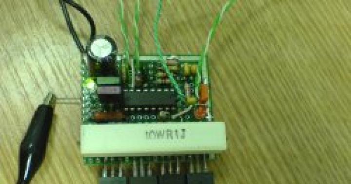
Recently it was necessary to test various very powerful batteries with voltages from 24 to 55 V. Since it is impossible to select resistors for such high currents, we had to build something completely electronic. The artificial load design served as the base. Since its power was too low, it intensified somewhat.
Electrical circuit diagram EN

The power element uses 8 0.68 Ohm resistors connected to an IGBT power transistor. Why IGBT? During testing, several conventional MOSFETs failed, but the IGBTs turned out to be noticeably more stable. Resistors are installed on radiators, 4 pcs each. Depending on the needs, they are connected in series for higher load voltages or in parallel for weaker ones. The radiators are screwed at a distance of 1 cm from the bottom of the case, holes are drilled under the radiators, the cooling air flow is significant.

The power transistor is installed on a heatsink from the PC processor and is cooled by two fans.

A 0.01 Ohm resistor is used as a measuring element and standard for the operational amplifier, and counters on ICL7107 microcircuits are used as meters - current accuracy is 0.1 A, voltage - 0.1 V.

Electrical power supply for meters and fans - taken from some kind of pulse device with parameters + 5 V at 5 A (indicators), +/- 12 V at 2 A (fans and op-amp). There was a cool metal case from some old device available, and it was decided to use it. The front panel is made from a piece of 3mm PVC plate. Holes for fans are cut out in the back.
Load operation test
- Circuit tested at 28V at 20A - power dissipated across 560W IGBT resistors and transistors - cooled and under load for one hour - 40 degree temperature.
- Another artificial load test was carried out with a 55 V battery at 11 A/h - here the load was 15 - 20 A, which means the power reached 1 kW - the radiators became hot, especially those on which power resistors were installed. The resistors heated up to about 110 degrees, the IGBT transistor to a temperature of 90 degrees, in principle acceptable.
- Naturally, you can easily test car batteries with a 12 V 20 A mode - the temperature was 80 degrees, which is normal.

Ways to improve the device
In the future, we will further improve this homemade electronic load by adding a power meter and a mode controller on Arduino (from Aliexpress).
The construction of the device was mainly spent on power resistors - the rest was lying around from disassembling all sorts of things.
Multiple sockets will also be added to allow multiple voltage ranges for testing without switching power resistors.